Installation – Campbell Scientific SDM-IO16 16-Channel Input/Output Expansion Module User Manual
Page 12
SDM-IO16 16 Channel Input/Output Expansion Module
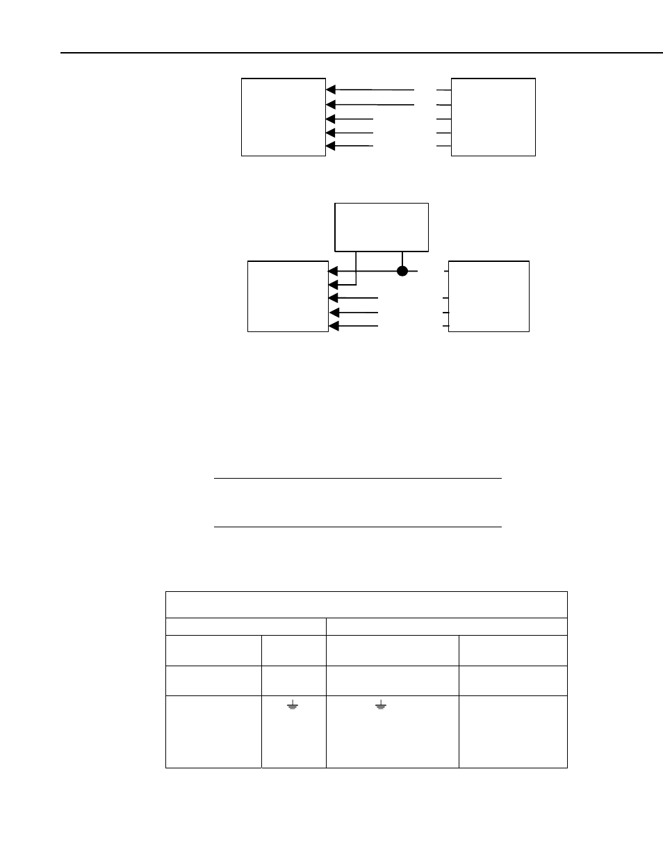
SDM-IO16
DATALOGGER
GND
12 V
SDM-C1 or C1
SDM-C2 or C2
SDM-C3 or C3
a) Connection with Datalogger Supply
EXTERNAL
9 TO 18 VDC
SDM-IO16
DATALOGGER
12 V
GND
+ -
SDM-C1 or C1
SDM-C2 or C2
SDM-C3 or C3
(b) Connection with External Supply
FIGURE 3. Connection Block Diagrams
4. Installation
For correct operation the SDM-IO16 must be installed where there is no risk of
water ingress or condensation.
The order in which connections are made is critical.
Always connect 12 V first, followed by ground, then the
control ports.
CAUTION
The CABLE5CBL-L or a similar cable connects the datalogger to the
SDM-IO16. For datalogger connections, see Table 1, below. Please refer to
Figure 4 for details of how to use the spring-loaded terminals.
TABLE 1. Datalogger to SDM-IO16 Connections
Datalogger
Connection Order
SDM-IO16
CR800, CR850, CR1000,
CR10(X), 21X, CR7
CR3000, CR5000
First
12 V
12 V on datalogger or
external supply
12 V on datalogger or
external supply
Second
C1
C2
C3
or G
C1
C2
C3
G
SDM-C1
SDM-C2
SDM-C3
6