Warning, Installation – Samlex America SBC-2 User Manual
Page 2
3
2
INSTALLATION
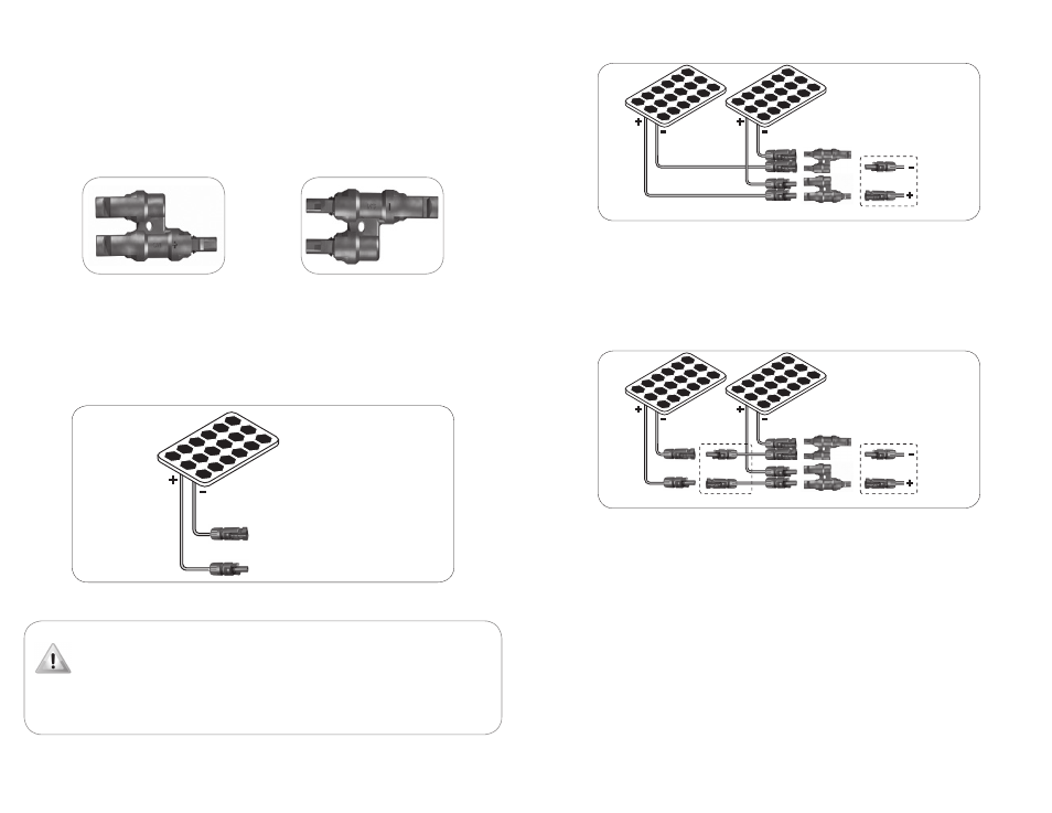
Connecting two adjacent solar panels in parallel (Fig. 4)
To external
PV circuit
Female MC4
connector
Male MC4
connector
SCW-20-2 Kit
Male
branch connector (+)
Female
branch connector (-)
Fig. 4. Connecting two adjacent solar panels in parallel
Two or more solar panels are connected in parallel to increase the current output at the same voltage.
Fig. 4 above shows the arrangement for connecting two solar panels in parallel using the SCW-20-2
Connecting Wire Kit (sold separately) and the Branch Connectors. This arrangement is possible if
the two solar panels will be mounted adjacent to each other.
The output wires of the two solar panels are connected in parallel using the Male and Female Branch
Connectors. The outputs of the Branch Connectors are then connected to the SCW-20-2 wires which connect
to the external PV circuit.
Connecting two solar panels in parallel when separated by a distance (Fig. 5)
To external
PV circuit
Female MC4
connector
Male MC4
connector
SCW-20-2 Kit
SCW-20-2 Kit
Male
branch connector (+)
Female
branch connector (-)
Fig. 5. Connecting two solar panels in parallel that are separated by an extended distance
Fig. 5 above shows an arrangement for connecting two solar panels in parallel when they are separated by an
extended distance. In this case, the following will be required:
• SCW-20-2 Connecting Wires - 2 sets (sold separately)
• One Male Branch Connector and one Female Branch Connector
• One MC4 Male Connector and one MC4 Female Connector (sold separately) Model: MC4-2
Use one pair of the connecting wires and the MC4 male/female connectors to bridge the extended distance
between the panels. The Branch Connectors are then used to parallel the two solar panels. Use the second
pair of connecting wires to connect to the external PV circuit.
Connect the MC4 connectors to the bare ends of each of the Connecting Wires as follows:
1. Cut the two SWC-20-2 wires to the desired lengths depending upon the distance between the solar panels.
2. Strip 0.25” of the insulation at the ends.
3. Establish the correct polarity by tracing the wires back to the solar panel, if necessary.
4. Crimp the male and female contact inserts (2 and 5 of Fig. 1) to the bare ends of the wire with the
help of special purpose crimping tool meant for the MC4 connectors.
5. Install the contact inserts inside the housing of the MC4 connectors and tighten the strain relief / seal (7 of
Fig. 1) fully to ensure a watertight seal.
Branch Connectors (Fig. 2a and 2B)
Branch Connectors are used to connect two MC4 Connectors in parallel.
Each Branch Connector has 3 branches - two on the one side & one on the other. The branches could be
"male" or "female". The construction of the branches is similar to the construction of the MC4 connectors
shown in Fig. 1. In a branch connector, all the 3 branches are internally connected in parallel.
A Male Branch Connector (marked "+") is shown in Fig 2A. This consists of two MC4 Male Connectors that are
connected in parallel with a MC4 Female Connector (marked "+"). This is used to connect two MC4 Female
Connectors in parallel.
A Female Branch Connector (marked "-") is shown in Fig 2B. This consists of two MC4 Female Connectors that
are connected in parallel with a MC4 Male Connector (marked "-"). This is used to connect two MC4 Male
Connectors in parallel.
Fig. 2A. Male Branch Connector (marked "+")
Fig. 2B. Female Branch Connector (marked "-")
wire Connections on Solar Panels (See Fig. 3)
Most solar panels come with approximately 3 ft of Positive (‘+’) and Negative (‘-‘) wire. One end of each
wire is connected to the junction box of the panel. The other end of each wire is terminated with an MC4
connector (all Samlex Solar Panel wires are confi gured this way). The Positive (‘+’) wire has a Female MC4
Connector and the Negative (‘-‘) wire has a Male MC-4 Connector. To extend the length of these wires for
connection to a charge controller, combiner box or grid-connected inverter, the extension wire is required to
be terminated with corresponding Male and Female MC4 Connectors.
Solar Panel
MC4 Male Connector (Marked “-”)
MC4 Female Connector (Marked “+”)
Fig 3. Solar panel connecting wires with MC4 Connectors
warning!
When the surface of the solar panel / array is exposed to sunlight, a DC voltage appears at the
output terminals turning it into a live voltage source. For example, a 24 V nominal solar panel
may put out an open circuit voltage of around 45 VDC that may produce electrical shock. Multiple
solar panels connected in series (to increase the output voltage) will put out higher lethal
voltages To avoid any electrical shock hazard during installation, make sure that the solar panel /
array is covered with an opaque (dark) material to block solar irradiation .