Samlex America Solsum_F User Manual
Operating manual
Operating manual
Solar charge controller
10.10 A / 8.8 A / 6.6 A
Please read these instructions comp
letely
before installation!
1.
A
bout thi
s manual
T
h
ese oper
ati
n
g i
n
str
u
cti
o
ns ar
e
par
t
of
the pr
oduct. R
ead these oper
ati
n
g i
n
str
u
cti
ons
car
e
fu
lly
bef
o
re
use, keep them ov
er
the enti
re l
ifeti
m
e of
the pr
oduct, and pass them on to
any
f
u
tur
e
ow
ner
or
user
of
thi
s pr
oduct.
T
h
is
manual
descr
ibes
the i
n
stal
la
tion, f
u
ncti
on, oper
ati
on and mai
n
tenance of
the sol
a
r
char
ge
contr
o
lle
r.
T
hese oper
ati
n
g i
n
str
u
cti
o
ns ar
e i
n
tended f
o
r end customer
s.
A techni
cal
ex
per
t must be consul
ted i
n
cases of
uncer
tai
n
ty
.
2. Safety
T
h
e
solar
charg
e
controller m
a
y only
be us
ed in PV sy
stem
s f
o
r charg
ing
and controlling
lead-
aci
d
batter
ies
in
accor
d
ance w
ith thi
s oper
ati
n
g manual
and the char
gi
ng
speci
fic
ati
ons of
the batter
y manuf
actur
e
r.
T
h
e
sol
a
r
char
ge
contr
o
lle
r may
onl
y be connected to the l
o
cal
l
oads and the batter
y by
tr
ai
ned per
sonnel
and i
n
accor
d
ance w
ith the appl
ic
abl
e r
e
gu
la
tions. Fol
lo
w
the
in
stal
la
tion
and oper
ati
n
g i
n
str
u
cti
o
ns f
o
r al
l components of
the PV sy
stem.
N
o
ener
gy
sour
ce
other
than
a sol
a
r g
e
ner
a
tor
may
be connected to the sol
a
r char
ge
contr
o
lle
r.
Fol
lo
w
the g
ener
al
and nati
onal
saf
e
ty
and acci
dent pr
ev
enti
on r
e
gu
la
tions.
Keep chi
ld
ren aw
ay
f
rom PV sy
stems. D
o
not
use
the
sol
a
r
char
ge
contr
o
lle
r
in
dusty
env
ironments, i
n
the v
ici
ni
ty
of
sol
vents or
w
h
er
e i
n
flammabl
e g
a
ses
and
vapour
s
can
occur
.
N
o
open
fir
e
s, f
lames or
spar
ks i
n
the v
ici
ni
ty
of
the batter
ies. Ensur
e
that the r
oom
is
adeq
u
atel
y v
enti
la
ted. C
heck the char
gi
ng
pr
ocess r
e
gu
la
rly
.
Fol
lo
w
the char
gi
ng
in
str
u
cti
ons of
the batter
y manuf
a
ctur
er
. Batter
y Aci
d
spl
a
shes on ski
n
or
cl
othi
ng
shoul
d be i
mmedi
atel
y r
inse w
ith pl
enty
of
w
a
ter
. Seek medi
cal
adv
ic
e.
D
o
not
oper
ate
the
sol
a
r
char
ge
contr
o
lle
r w
hen i
t does not appear
to f
uncti
on at al
l. T
he
sol
a
r char
ge
contr
o
lle
r or
connected cabl
es ar
e v
isi
bl
y damag
ed or
l
oose.
In
these
cases
immedi
atel
y r
e
mov
e
the sol
a
r char
ge
contr
o
lle
r f
rom the sol
a
r modul
es and batter
y.
3.
Functi
ons
T
h
e sol
a
r char
ge
contr
o
lle
r moni
tor
s the state
of
char
ge
of
the batter
y bank, contr
o
ls
the
char
gi
ng
pr
ocess, contr
o
ls
the connecti
on/di
sconnecti
on of
l
oads.
T
h
is
opti
m
is
es
batter
y
use and si
gn
ifi
cantl
y ex
tends i
ts ser
vi
ce l
ife.
T
h
e f
o
llo
w
ing
pr
otecti
on f
uncti
ons ar
e par
t of
the basi
c f
uncti
on of
the contr
o
lle
r:
Ov
er
char
ge
pr
otecti
on
; D
eep di
schar
ge
pr
otecti
on
; Batter
y under
vo
ltag
e pr
otecti
on
;
Sol
a
r
modul
e
r
e
ve
rs
e cur
rent pr
otecti
on.
4. In
stallatio
n
4.1 M
o
unti
n
g l
o
cati
on r
e
qu
irements
D
o
not mount the sol
a
r char
ge
contr
o
lle
r outdoor
s or
in
w
e
t r
ooms. D
o
not subj
ect
the
sol
a
r
char
ge
contr
o
lle
r
to
di
re
ct
sunshi
ne
or
other
sour
ces of
heat. Pr
otect the sol
a
r char
ge
contr
o
lle
r f
rom di
rt
and moi
stur
e
.
M
ount upr
ig
h
t on the w
a
ll (
concr
ete)
on a
non-
flammabl
e
substr
ate.
M
a
in
tai
n
a
mi
ni
mum
cl
ear
ance
of
10
cm
bel
ow
and
ar
ound the dev
ice to ensur
e unhi
nder
ed ai
r ci
rc
ul
ati
on.
M
ount the sol
a
r char
ge
contr
o
lle
r as cl
ose as possi
bl
e to the batter
ies
(w
ith
a
saf
e
ty
cl
ear
ance of
at l
east 30 cm)
.
4.2 Fasteni
ng
the sol
a
r char
ge
contr
o
lle
r
M
a
rk
the posi
tion of
the sol
a
r char
ge
contr
o
lle
r f
a
steni
ng
hol
es on the w
a
ll.
Drill 4
Ø 6
m
m
h
o
le
s a
n
d
in
se
rt d
o
w
e
ls. Fa
ste
n
th
e
so
la
r
ch
a
rge
co
n
tro
lle
r
to
th
e
w
a
ll
w
ith
the cabl
e openi
n
gs
f
a
ci
ng
dow
nw
ar
ds, usi
n
g 4 ov
al
head scr
ew
s M
4
x40 (
D
IN
7996)
.
4.3 C
o
nnecti
on
U
se
an
w
ire
si
ze
sui
ted
to
the
cur
re
nt
ra
ting
s of
the char
ge
contr
o
lle
r,
e.g
. 6mm²
f
o
r 10A, 5
mm²
f
o
r 8A, 4 mm²
f
o
r 6A, 3 mm²
f
o
r 5A f
o
r cabl
e l
e
ng
th of
10 m.
An addi
tional
ex
ter
nal
20A f
u
se (
n
ot pr
ov
id
ed)
must be
connected
to
the
batter
y
connecti
on
cabl
e, cl
ose to the batter
y pol
e. T
he ex
ter
n
al
f
u
se pr
ev
ents cabl
e shor
t ci
rc
ui
ts.
Sol
a
r modul
e
s g
ener
ate el
ectr
ic
ity
under
i
n
ci
dent l
ig
ht. T
he
fu
ll
vo
ltag
e
is
pr
esent,
ev
en
w
h
en the i
n
ci
dent l
ig
ht l
e
ve
ls
ar
e l
o
w
. Pr
otect the sol
a
r modul
es f
rom
in
ci
dent
lig
ht
dur
in
g
installation, e.g
. cov
e
r them.
N
e
ve
r touch not i
sol
ated cabl
e ends. U
se onl
y i
n
sul
a
ted tool
s. Ensur
e
that al
l l
oads to be
connected ar
e sw
itched of
f.
If
necessar
y, r
e
mov
e
the f
u
se.
C
onnecti
ons must al
w
a
ys
be made i
n
the seq
u
ence descr
ibed bel
ow
.
1st step:
Connect the battery
C
onnect
the batter
y connecti
on cabl
e w
ith the
cor
re
ct pol
ar
ity
to the mi
ddl
e
pai
r
of
ter
m
in
al
s
o
n
t
h
e
so
la
r
ch
a
rge
co
n
tro
lle
r (w
ith
t
h
e
b
a
tt
e
ry
sy
mbol
).
If
pr
esent, r
e
mov
e
any
ex
ter
n
al
f
u
se. C
o
nnect
batter
y connecti
on cabl
e A+
to the posi
tiv
e
pol
e
of
the batter
y. C
o
nnect batter
y
connecti
o
n
cabl
e A– to the neg
a
tiv
e
pol
e of
the batter
y. Inser
t the ex
ter
nal f
u
se in
the
batter
y connecti
on cabl
e.
If
the connection polar
ity
is cor
re
ct, the
inf
o
L
E
D illu
m
in
a
te
s gre
e
n
.
2nd step: Connect the sol
ar
modul
e
Ensur
e
that the sol
a
r modul
e
is
pr
otected f
rom
incident lig
ht (
cov
er
it or
w
a
it f
o
r nig
h
t)
.
Ensur
e
that the sol
a
r modul
e
does not ex
ceed the max
imum per
m
issi
bl
e i
nput cur
rent.
Fi
rs
t connect the M
+
sol
a
r modul
e
connecti
on cabl
e to
the
cor
re
ct
pol
e
of
the
le
ft
pai
r
of
ter
m
in
al
s on the sol
a
r char
ge
contr
o
lle
r (
w
ith the sol
a
r modul
e
sy
mbol
),
then connect the
M
–
cable. Remov
e
the cov
e
ring
f
rom the solar
module.
3rd step:
Connect loads
Fi
rs
t connect the L+
load cabl
e to the cor
re
ct pol
e
of
the
rig
h
t
pai
r
of
ter
m
in
al
s
on
the
sol
a
r
char
ge
contr
o
lle
r
(w
ith
the
la
mp
sy
mbol
),
then connect the L– cabl
e. Inser
t the l
oad f
u
se or
sw
itch on the l
oad.
N
o
tes :
C
onnect l
oads that must not be deacti
va
ted by
the
sol
a
r
char
ge
contr
o
lle
r
deep
di
schar
ge
pr
otecti
on,
e.g
.
emer
ge
ncy
l
ig
hts
or
r
a
di
o connecti
on, di
re
ctl
y to the batter
y.
Loads w
ith a hi
gher
cur
rent consumpti
on than the dev
ic
e output
can
be
di
re
ctl
y
connected
to
th
e
b
a
tte
ry
. Ho
w
e
ve
r, th
e
so
la
r ch
a
rge
co
n
tro
lle
r
d
e
e
p
d
isch
a
rge
p
ro
te
ctio
n
w
ill
n
o
lo
n
ge
r
in
ter
vene. Loads connected i
n
thi
s manner
must al
so be separ
atel
y f
u
sed.
4th step:
Final w
o
rk
Fa
ste
n
a
ll ca
b
le
s w
ith
stra
in
re
lie
f in
th
e
d
irect v
icinity
of
the
so
la
r ch
a
rge
co
n
tro
lle
r
(c
lear
ance of
appr
ox
. 10 cm)
.
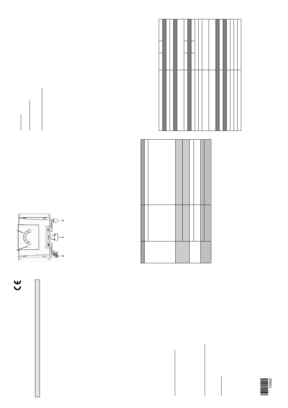
5.
LED di
spl
ay
s
LED
Status
M
eaning
illum
inates g
reen
norm
al operation
Inf
o
LED
flashes sl
ow
ly
r
e
d*
sy
stem f
aul
t
- too hi
gh
char
gi
ng
cur
re
nt
- ov
er
load / shor
t ci
rc
ui
t
- ov
er
heated
tog
e
ther
w
ith r
e
d LED :
- too l
o
w
batter
y v
o
ltag
e
tog
e
ther
w
ith g
reen LED :
- too hi
gh
batter
y v
o
ltag
e
flashi
ng
q
u
ickl
y*
batter
y empty
, l
o
w
v
o
ltag
e di
sconnecti
on
p
re
w
a
rn
in
g, lo
a
d
s still o
n
Batter
y
red
LED
flashi
ng
sl
ow
ly
*
deep di
schar
ge
pr
otecti
on acti
ve
(
L
VD
),
lo
ads
di
sconnected
illu
m
in
a
te
s
b
a
tte
ry
w
e
a
k, lo
a
d
s a
re
o
n
Batter
y
ye
llo
w
LED
flashes sl
ow
ly
y
e
llo
w
*
LVD
r
e
connecti
on setpoi
nt has not y
e
t been
reached, loads still disconnected
illu
m
in
a
te
s
batter
y g
o
od
Batter
y
gr
een
LED
flashes q
u
ickl
y g
reen*
batter
y f
u
ll, char
ge
r
e
gu
lation activ
e
*f
la
shi
n
g sl
ow
ly
: 0,4H
z:
4 ti
mes i
n
10 second, f
lashi
ng
q
u
ickl
y:
3H
z:
3 ti
mes i
n
1 second
6.
Gr
oundi
ng
T
h
e
components
in
stand-
al
one sy
stems do not hav
e to be g
rounded – thi
s i
s not standar
d
pr
acti
ce or
may
be pr
ohi
b
ited by
nati
onal
r
e
gu
la
tions (
e
.g
.: D
IN
57100 Par
t
410:
Pr
ohi
bi
tion
of
g
roundi
ng
pr
otecti
ve
lo
w
v
o
ltag
e ci
rc
ui
ts)
. Ask y
our
deal
er
f
o
r techni
cal
assi
stance.
7.
Li
ghtni
ng pr
otecti
on
In sy
stems subj
ected to an i
n
cr
eased r
isk of
ov
er
vo
ltag
e damag
e
, w
e
r
e
commend
installing
additional lig
htning
protection / ov
erv
oltag
e protection to
reduce dropouts.
Ask y
our
deal
e
r f
o
r te
chnical assistance.
8. M
aintenance
T
h
e
so
la
r ch
a
rge
co
n
tro
lle
r is m
a
in
te
n
a
n
ce
-f
re
e
.
Al
l components of
the PV sy
stem must be checked at l
east annual
ly
, accor
d
in
g
to
the
speci
fic
ati
ons of
the r
e
specti
ve
manuf
a
ctur
er
s. Ensur
e
adeq
uate v
e
nti
la
tion of
the
cool
in
g
el
ement. C
heck the cabl
e str
a
in
r
e
lie
f.
C
h
eck that al
l cabl
e
connecti
ons
ar
e
secur
e
.
T
ig
h
ten
screw
s if
necessary
. Check
cor
ro
si
on on ter
m
inal
s.
9.
Faul
ts and r
emedi
es
No
d
isp
la
y
: C
h
eck batter
y pol
ar
ity
and ex
ter
n
al
f
u
se. Or
batter
y v
o
ltag
e i
s
too
lo
w
or
batter
y def
e
ctiv
e.
Batter
y is not
char
ge
d
: C
h
eck i
f sol
a
r modul
i
s connected w
ith cor
re
ct pol
ar
ity
or
i
f shor
t
ci
rc
ui
t at the sol
a
r i
n
put. If
sol
a
r modul
e v
o
ltag
e i
s l
o
w
e
r than
batter
y
vo
ltag
e
or
i
f
sol
a
r
modul
e i
s def
ecti
ve
the batter
y cannot be char
ge
d.
Battery
display
s jum
p
s q
u
ickly
:
Batter
y v
o
ltag
e chang
es q
u
ickl
y.
Lar
ge pul
se cur
rents
cause
vo
ltag
e
fluctuati
o
n.
Batter
y
is
too smal
l or
def
ecti
ve
. Ask y
our
deal
er
f
o
r techni
cal
assistance.
T
h
e
f
o
llo
w
in
g
fa
u
lts
d
o
n
o
t
d
e
stro
y th
e
co
n
tro
lle
r. A
fte
r co
rre
ctin
g th
e
f
a
u
lt, th
e
d
e
vi
ce
w
ill
conti
nue to oper
a
te cor
re
ctl
y:
* sol
a
r modul
e
shor
t ci
rc
ui
ts
* r
e
ve
rs
e sol
a
r modul
e
pol
ar
ity
*2
* shor
t ci
rc
ui
ts at l
oad output
* ex
cessi
ve
lo
ad cur
re
nt
* re
ve
rse
d
b
a
tt
e
ry
p
o
la
rit
y
*1
* so
la
r m
o
d
u
le
o
ve
rcu
rre
n
t
* dev
ic
e ov
er
temper
atur
e
* ov
er
vo
ltag
e at the l
o
ad output
10.
Legal
guar
antee
Accor
d
in
g
to
the
Ger
m
an
le
ga
l r
e
qu
irements, f
o
r thi
s pr
oduct the customer
has a 2 y
e
ar
le
ga
l gu
a
ra
n
te
e
.
T
he seller w
ill rem
o
ve
all m
a
nuf
a
cturing
and m
a
terial f
a
ults th
at occur in the product
during
the l
e
ga
l g
u
ar
antee per
iod and af
fe
ct the cor
re
ct f
uncti
oni
ng
of
the pr
oduct. N
a
tur
a
l w
e
ar
and tear
does not consti
tute a mal
functi
on.
Leg
a
l g
uar
antee does not appl
y i
f the f
aul
t can be attr
ibuted to thi
rd par
tie
s,
unpr
of
essi
onal
in
stal
la
tion or
commi
ssi
oni
ng
, i
n
cor
re
ct or
neg
lig
ent
handl
in
g,
im
pr
oper
tr
anspor
t,
ex
cessi
ve
loadi
n
g,
use of
i
m
pr
oper
eq
ui
pment, f
a
ul
ty
constr
ucti
on
w
o
rk
,
unsui
tabl
e
constr
ucti
on
lo
cati
on or
im
pr
oper
oper
a
tion or
use.
Leg
a
l
guar
antee
cl
ai
ms
shal
l onl
y be accepted i
f noti
fic
ati
on of
the f
a
ul
t i
s pr
ov
ided
immedi
atel
y
af
ter
i
t
is
di
scov
e
red.
Leg
al
g
u
ar
antee cl
ai
ms ar
e to be di
re
cted to the sel
le
r.
T
he sel
le
r must be i
n
fo
rm
ed bef
o
re
le
ga
l g
uar
antee cl
ai
ms ar
e pr
ocessed.
For
pr
ocessi
ng
a l
e
ga
l g
uar
antee cl
ai
m an ex
act f
aul
t descr
ip
tion and the i
n
vo
ic
e
/
del
iv
er
y
note must be pr
ov
id
ed. T
he sel
le
r can choose to f
u
lfi
l the l
e
ga
l g
uar
antee
ei
ther
by
r
epai
r
or
repl
acement.
If
the pr
oduct can nei
ther
be r
e
pai
re
d nor
r
e
pl
aced, or
i
f thi
s does not occur
w
ithi
n
a
sui
tabl
e
per
io
d
in
spi
te of
the speci
fic
ati
on of
an ex
tensi
on per
io
d i
n
w
rit
in
g by
the
customer
,
the
reducti
on
in
v
a
lue
caused
by
the f
a
ul
t shal
l be r
e
pl
aced, or
, i
f thi
s i
s not
suf
fici
ent taki
ng
the i
n
ter
e
sts of
the end customer
i
n
to consi
d
er
ati
on, the
contr
a
ct
is
cancel
led. Any
f
u
rt
her
cl
ai
ms ag
ai
nst the sel
le
r based
on
thi
s
le
ga
l g
uar
antee
obl
ig
ati
on,
in
par
tic
ul
ar
cl
ai
ms f
o
r damag
e
s due to l
o
st pr
of
it, l
o
ss-
of
-u
se
or
indi
re
ct
damag
es
ar
e
ex
cluded, unless liability
is
oblig
atory
by
Germ
an law
.
11. Technical Data
St
eca Solsum F
6.6F
8.8F
10.10F
C
h
aract
e
risat
ion of
t
h
e operating performance
Sy
stem v
o
ltag
e
12 V (
24 V)
Ow
n consumpti
on
<
4 mA
DC input side
Open ci
rc
ui
t v
o
ltag
e sol
a
r modul
e
(a
t mi
ni
mum oper
ati
n
g temper
atur
e)
<
47 V
M
odul
e cur
re
nt
6 A
8 A
10 A
DC output side
Load cur
rent
6 A
8 A
10 A
End of
char
ge
v
o
ltag
e
13.9 V (
27.8 V)
Boost char
ge
v
o
ltag
e
14.4 V (
28.8 V)
R
e
connecti
on v
o
ltag
e (
S
OC
/ LVR
) *³
>
50 % / 12.4 V … 12.7 V
(24.8 V … 25.4 V)
D
eep di
schar
ge
pr
otecti
on (
S
OC
/ LVD
) *³
<
30 % / 11.2 V … 11.6 V
(22.4 V … 23.2 V)
Operating conditions
Ambi
ent temper
atur
e
-2
5 °C
… +
50 °C
Fitting and c
onstruction
T
e
rm
in
a
l (f
in
e
/
sin
gle
w
ire
)
4
m
m
2
/ 6 mm
2
-
AW
G 12 / 9
D
e
gr
ee of
pr
otecti
on
IP 32
D
im
ensi
ons (
X
x
Y
x
Z)
145 x
100 x
24 mm
W
e
ig
ht
appr
ox
. 150 g
*1
Sol
sum i
s pr
otected ag
ai
nst r
e
ve
rs
e batter
y pol
a
rity
tog
e
ther
w
ith
pol
a
rity
pr
otected
loads.
R
e
ve
rs
e
batter
y
pol
ar
ity
combi
n
ed w
ith shor
t ci
rc
ui
ted or
pol
a
rised l
o
ad coul
d
cause damag
e
s i
n
load or
r
e
gu
la
tor
*2
Av
oi
d r
e
ve
rs
e modul
e
pol
ar
ity
in
a 24V sy
stem
*3
Low
e
r v
a
lu
e f
o
r nomi
nal
cur
rent, hi
gh
er
v
a
lu
e f
o
r l
o
w
e
st cur
re
nt
In
fo
LE
D
Ba
tt
ery
LE
D
s
Manufac
tured in a
DIN E
N
ISO 9001:
2000 facility
Sols
um
/ Z
02
/ Ver
sion 1104
/ 730.930