Installation – Samlex America DC-BTS-A-C User Manual
Page 2
2
2. It consists of a sensing element that is embedded in the ring terminal
• (1, Fig 1). This sensor is attached to 10 meters of two wire, color coded
cable (4, Fig 1). The cable is polarized i.e. red wire has Positive polarity
and the black wire with red stripe has Negative polarity. The other ends
of the wires
•
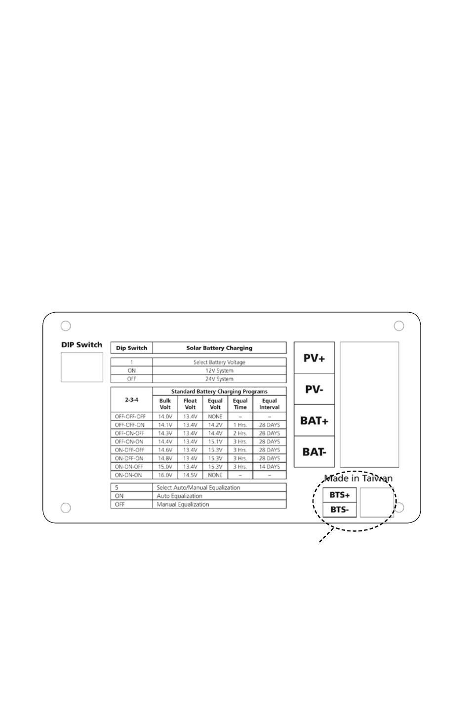
(2, 3, Fig 1) are bare and are required to be connected to the terminals
on the charge controller marked BTS+ and BTS– (Fig 2).
3. Detailed operation of the Battery Temperature Sensor is further explained in
the Owner’s manual for the Charge Controller Model No.SCC-30AB
InstallatIon
Connect the wires of the Temperature Sensor here.
Fig 2 Wiring connections on the back of the Charge Controller Model No. SCC-30AB
Note: Voltages shown below are for 12V battery.
For 24V battery, multiply these voltages by 2.
- SEC-1212 (16 pages)
- SEC-1223BBM (24 pages)
- SEC-1235 (16 pages)
- SEC-1212CE (12 pages)
- SEC-1223BBM-230 (24 pages)
- SEC-40BRM (24 pages)
- SEC-2430BRM (24 pages)
- SEC-4825BRM (36 pages)
- SEC-40BRM-220 (24 pages)
- SAM-1000-12 (32 pages)
- SAM-450-12E (16 pages)
- SAM-RC (8 pages)
- SAM-1500C-12 (32 pages)
- PST-300-12 (44 pages)
- PST-120-12 (12 pages)
- PST-600-12 (48 pages)
- PST-1500-12 (48 pages)
- RC-15A (8 pages)
- RC-200 (8 pages)
- PST-15S-12A (32 pages)
- PST-15S-12E (48 pages)
- PST-60S-12E (48 pages)
- SA-150 (15 pages)
- SA-600R (20 pages)
- SA-1000K (23 pages)
- SA-1500 (34 pages)
- SA-2000K (21 pages)
- SK (26 pages)
- SK (25 pages)
- SK120 (20 pages)
- S600 (24 pages)
- S1500 (39 pages)
- PSE-12125A (36 pages)
- PSE-24125A (36 pages)
- TN-1500 (20 pages)
- ST1000-112 (26 pages)
- ST1500-124 (40 pages)
- SR1000-124 (37 pages)
- BP-1210 (11 pages)
- BW-01 (2 pages)
- BATTERY MONITOR BW-03 (4 pages)
- SC-05 (12 pages)
- BBM-1225 (12 pages)
- BBM-12100 (12 pages)
- IDC-100 (4 pages)