Principle of operation – Samlex America BBM-1225 User Manual
Page 4
PRINCIPLE OF OPERATION
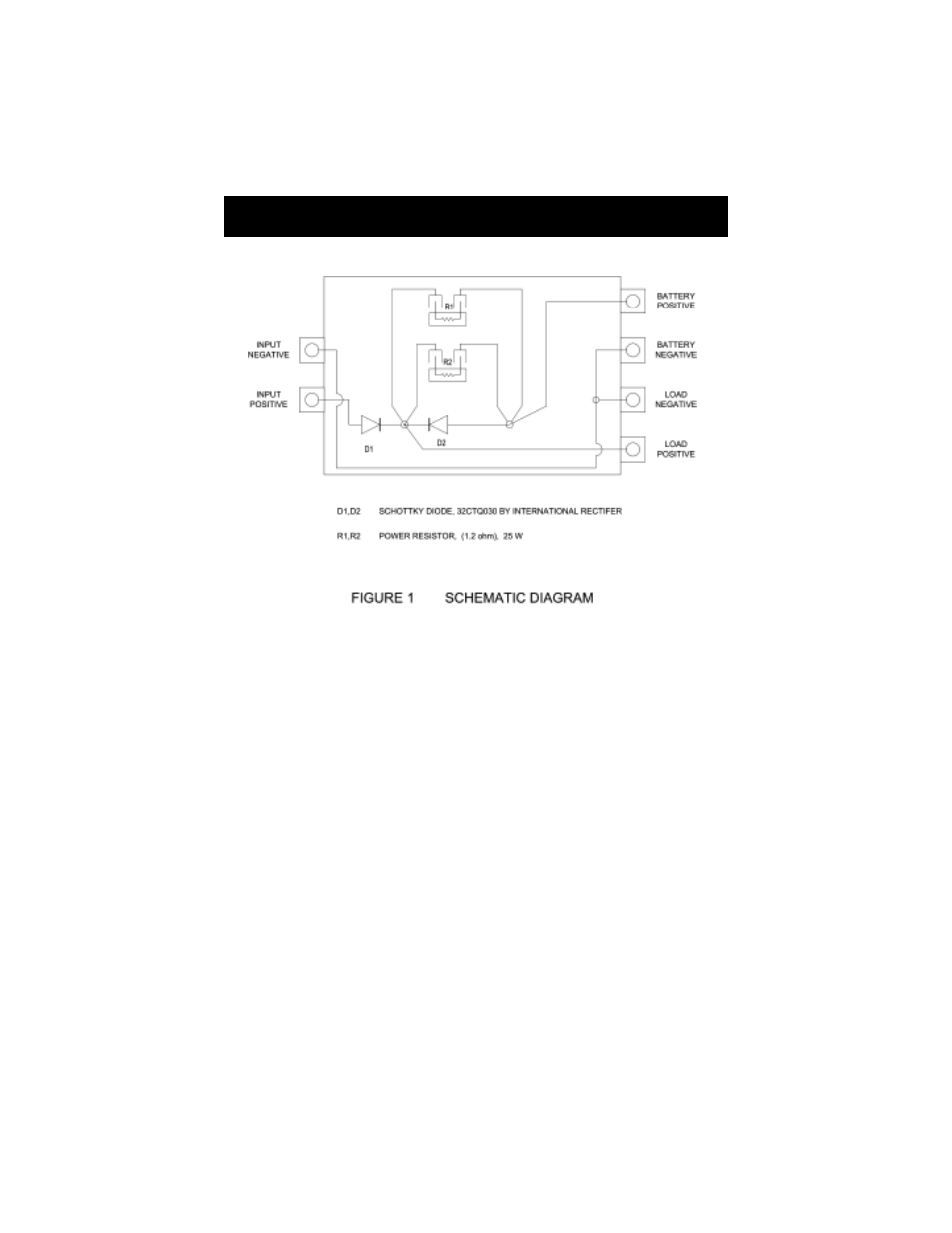
Please refer to the schematic diagram at Fig. 1
The power supply is connected to the positive and negative input terminals. The
battery is connected (through a fast acting fuse of the appropriate current
capacity) to the battery terminals and the load is connected to the load terminals.
The voltage from the power supply is fed through the isolating Schottky diode
D1 to the load and to the battery through the charging current limiting resistors
R1 and R2. Diode D1 provides isolation between the power supply and the
battery to prevent the battery from feeding back into the power supply circuit.
D1 has a forward voltage drop of 0.4 (at < 1 A) to 0.5 V (at > 10 A). Hence, the
voltage available to the load and to the battery for float charging will be 0.4 to
0.5 V lower than the output voltage of the power supply. In a battery backup
application, the battery will normally remain in a fully charged, standby
condition most of the time. It will discharge to the load only when the power
supply fails. Under this standby application, the battery should be charged
at the recommended float voltage. Assuming the standby float charging
voltages of 12 V / 24 V sealed lead acid (SLA) batteries to be 13.5 V to 13.8 V
and 27 V to 27.6 V ( at 60ºF to 77ºF) respectively, the output voltage of the
power supply should be adjusted as follows:
Page 3