Battery monitor bw-03 | owner's manual, Bw-03, Table 1: programmable alarm settings – Samlex America BATTERY MONITOR BW-03 User Manual
Page 2: 1a to 1d 2 3, Legend
SAMLEX AMERICA, INC.
| 2
BATTERY MONITOR BW-03 |
OWNER'S MANuAL
After the last programmable value has been set, the display switches OFF for
a moment once again and BW-03 functions normally again. This set value is
memorised if BW-03 is (temporarily) de-energised.
Table 1: Programmable Alarm Settings
sPecificatiOns
Parameter
12V
24V
Supply Voltage Range
6VDC to 31VDC
Nominal Battery Voltage
12V / 24V, Auto Sensing
Display
3 Digit, 7 Segment LED Display; Accuracy: 0.1V
Current Consumption
Display ON
20mA
Display OFF
8mA
Power Save Mode
< 0.1mA
Programmable Voltage
Settings for Alarm
Under Voltage
12V (24V): 10.5V to 12.0V (21.0V to 24.0V)
Default: 10.8V (21.6V)
Over Voltage
12V (24V): 10.5V to 12.0V (29.2V to 23.8V)
Default: 14.8V (29.6V)
Alarm Output
Open Drain, 500 mA maximum
Switches to (-) of battery when alarm is activated
Input Connections
Terminal Block: Tubular Hole with set screw
Connecting Wire Size /
Fuse Rating
AWG # 18 to 20 or 0.75mm2 / 32V. 0.5A
Dimensions
Height / Diameter: 60mm
Depth: 20 mm
Diameter of Mounting Hole: 55mm
Mounting Depth: 18mm
Weight
200g
Materials
Housing: Anodized Aluminum
Top Label: Polycarbonate
Certifications
CE Marked; RoHS Compliant
undervoltage
Overvoltage
12V
24V
12V
24V
mV
1
10.5V
21.0V
14.6V
29.2V
*
- - -
2
10.6V
21.2V
14.7V
29.4V
400 mV
3
10.7V
21.4V
14.8V
*
29.6V
*
450 mV
4
10.8V
*
21.6V
*
14.9V
29.8V
500 mV
5
10.9V
21.8V
15.0V
23.0V
550 mV
6
11.0V
22.0V
15.1V
23.2V
600 mV
7
11.1V
22.2V
15.2V
23.4V
650 mV
8
11.2V
22.4V
15.3V
23.6V
700 mV
9
11.3V
22.6V
15.4V
23.8V
750 mV
10
11.4V
22.8V
800 mV
11
11.5V
23.0V
12
11.6V
23.2V
13
11.7V
23.4V
14
11.8V
23.6V
15
11.9V
23.8V
16
12.0V
24.0V
*
Default settings
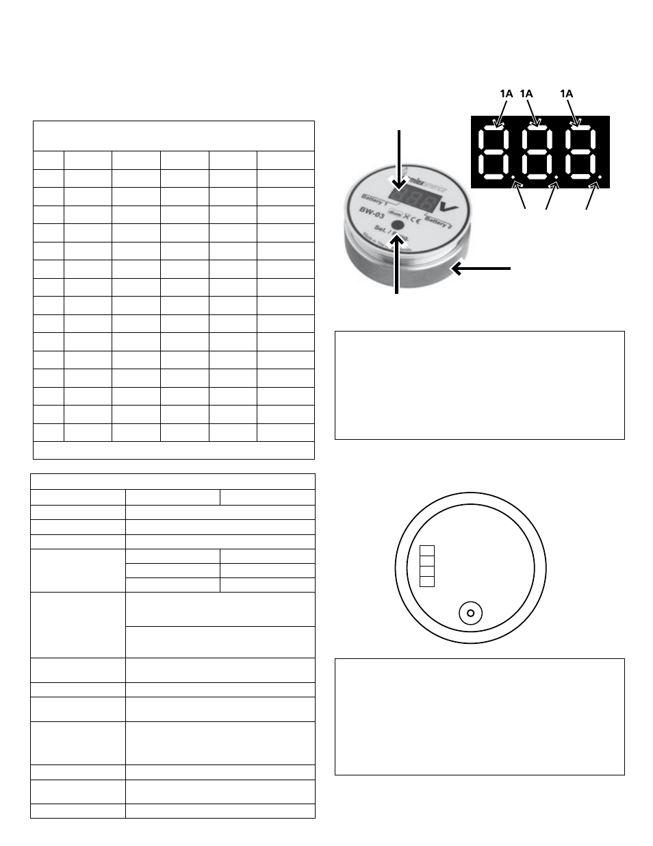
1A to 1D
2
3
1B 1C
1D
Fig 1A: Layout - Top of unit
LEGEND
NOTE: If 2 battery banks are connected, connect to BAT2 first
and then to BAT1.
OUT - Drain Pin of Open Drain; Max. 500 mA
BAT1 - Connection for Positive of Battery 1
BAT2 - Connection for Positive of Battery 2
MIN - Connection for Common Negative
Fig 1B: Layout - Back of unit
LEGEND
1A 3 Digit, 7 Segment. LED Display (Steps of 0.1V)
1B LED dot showing that voltage of Battery 1 is being displayed
1C LED dot showing decimal point for voltage reading
1D LED dot showing that voltage of Battery 2 is being displayed
2 Select / Programming Button
3 Knurled Ring Nut
OuT
BAT1
BAT2
MIN
BW-03