Dc input connection, Reducing rf interference, Ac side connections – Samlex America PST-1000-24 User Manual
Page 33: Warning! preventing paralleling of the ac output
32 | SAMLEX AMERICA INC.
SAMLEX AMERICA INC. | 33
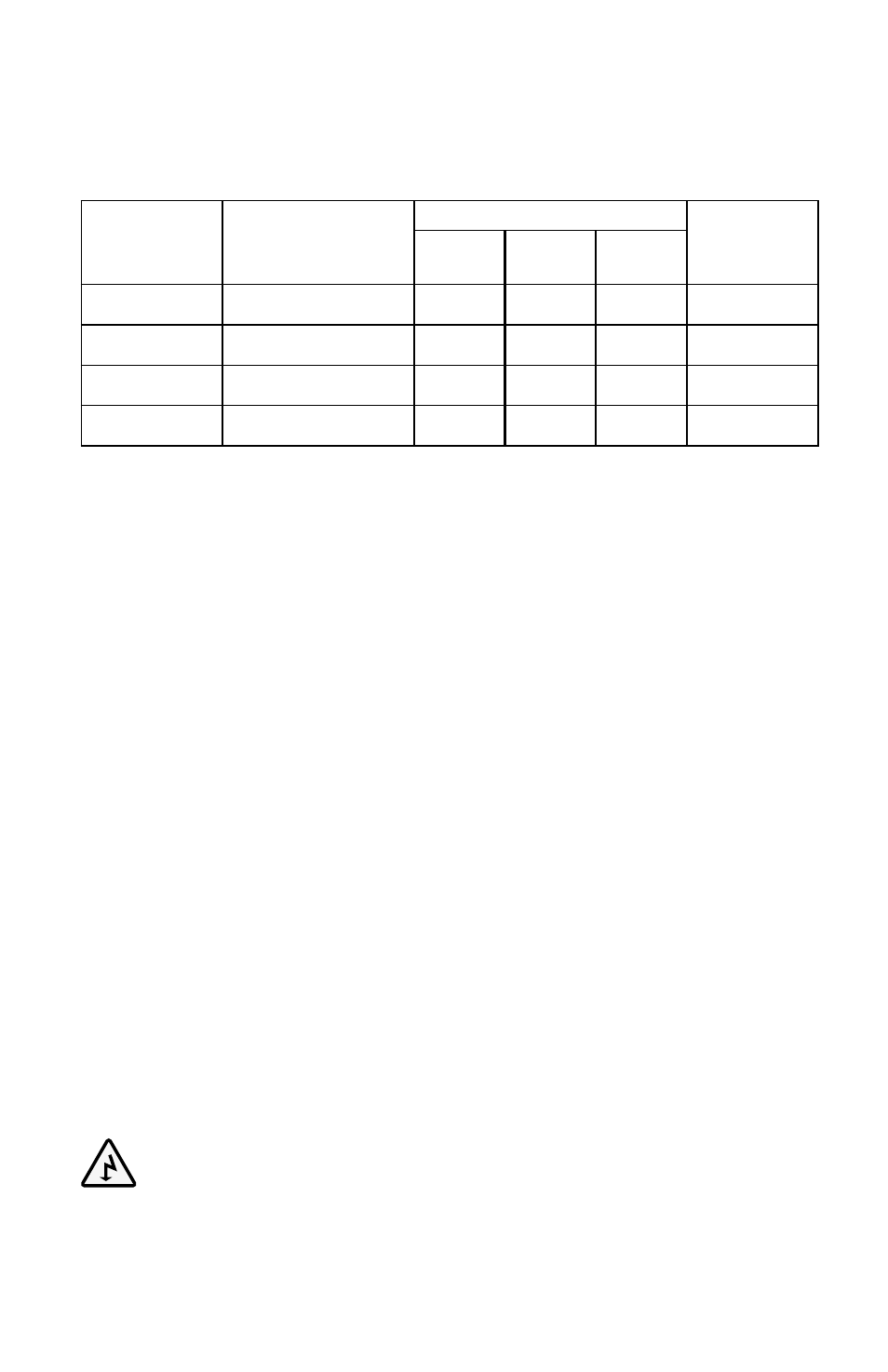
Model no.
Maximum Dc input
current at rated output
power & minimum rat-
ing of external fuse
Size of Wire
Samlex
America Dc
install Kit
0.91M /
3 ft.
1.83M /
6 ft.
3.05M /
10 ft.
PST-600-12
80A
AWG #6
AWG #2
AWG #1/0
DC-1000-KIT
PST-600-24
40A
AWG #8
AWG #8
AWG #6
DC-1000-KIT
PST-1000-12
160A
AWG #2
AWG #1/0
AWG #3/0
DC-2000-KIT
PST-1000-24
80A
AWG #6
AWG #6
AWG #4
DC-1000-KIT
*
NoTES:
1. The ampere carrying capacity (Ampacity) of various sizes of wires is based on NEC Table 310.17
for single, insulated conductors in free air at 104˚f / 40˚C ambient. The size is based on the fuse
rating.
2. The wire size is based on allowable ampacity or 2% voltage drop, whichever is thicker.
3. four standard models of Samlex America, Inc. DC Installation Kits are available to cover installa-
tion requirements of 600 to 3500W inverters. Voltage drop of 2% or less will be applicable for
3 ft. (.91 metres) distance. In some cases the kits may contain thicker cables and higher rated
fuses than the minimum sizes recommended. Thicker cables will produce lower voltage drop
and hence, will further improve the overall efficiency. Also, voltage drop may be > 2% in some
cases for distances > 3 ft. (.91 metres).
Dc input connection
The DC input terminals for battery connection (8 & 9 in fig. 6.1) have
cylindrical hole with set screw:
- Hole size for PST-600: 8 mm / .315" with M-8 set screw
- Hole size for PST-1000: 11 mm / .433" with M-8 set screw
Do NoT insert the stranded bare end of the wire directly into the tubular hole as the set
screw will not pinch all the strands, resulting in a partial/loose contact.
To ensure firm contact, a pair of pin type terminal lugs have been provided as follows:
• PST-600: for up to AWG#2 or 35 mm
2
wire size (Part No. PTNB 35-20)
• PST-1000: for up to AWG#1/0 or 50 mm
2
wire size (Part No. PTNB 50-20)
Reducing RF interference
Please comply with recommendations given in Section 3 on page 11 - "Limiting Electro-
magnetic Interference".
Ac SiDe connectionS
WARninG! Preventing Paralleling of the Ac output
1. The AC output of the inverter cannot be synchronized with another AC
source and hence, it is not suitable for paralleling. The AC output of the in-
verter should never be connected directly to an electrical breaker panel / load
seCtIOn 8 |
Installation