Samlex America SAM-450-12E User Manual
Page 6
6 | SAMLEX AMERICA INC.
seCtIOn 4 |
How Your Inverter works
The inverter converts low voltage DC
(Direct Current) from a battery or other
power source to standard 230 volt AC
(Alternating Current) household power.
PRinciPLe oF oPeRAtion
The inverter converts power in two stages.
The first stage is a DC to DC conversion
process that raises the low voltage DC at
the inverter input to around 300 volts DC.
The second stage is the actual inverter
stage that converts the high voltage DC
into 230 VAC, 50 Hz AC (rMS). The DC-
to-DC converter stage uses modern high
frequency power conversion techniques
that have replaced the bulky transformers
found in less technologically-advanced
models. The inverter stage uses advanced
power MoSfET transistors in a full bridge
configuration.
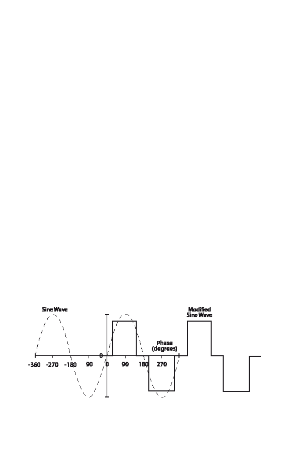
tHe oUtPUt WAVeFoRM
The AC output waveform of the SAM
Series inverter is known as “modified sine
wave”. It is a waveform that has charac-
teristics similar to the sine wave shape of
utility power. This type of waveform is
suitable for most AC loads, including lin-
ear and switching power supplies used in
electronic equipment, transformers, and
motors. (See fig. 1 below).
The modified sine wave produced by the
inverter has an rMS (root mean square)
voltage of 230 volts, which is the same as
standard household power. Most AC volt-
meters (both digital and analog) are sensi-
tive to the average value of the waveform
rather than the rMS value. They are cali-
brated for rMS voltage under the assump-
tion that the waveform measured will be
a pure sine wave. These meters will not
read the rMS voltage of a modified sine
wave correctly. They will read about 20 to
30 volts low when measuring the output
of the inverter. for accurate measurement
of the output voltage of this unit, use
a true rMS reading voltmeter such as a
fluke 87III, fluke 8060A, fluke 77/99 series
or beckman 4410.
Fig. 1: Modified Sine Wave and Sine Wave Comparison