Samlex America SEC-2450BRM User Manual
Page 10
7.
Regulated output voltage of 28VDC +/ - 1% from the modules ( measured at screw
terminals S5 and S6 (Fig.1) is fed to the positive and negative DC bus bars and from
there to the output terminals LOAD+ and LOAD- through the isolating Schottky Di-
ode D1. Although the output voltage at the module terminals S5 and S6 ( Fig.1) or at
the common DC bus bar (before the Schottky Diode D1) is tightly regulated at the
preset value of 28VDC +/ - 1%, the voltage at the output terminals Load + and Load
-
will vary slightly due to the forward voltage drop of the isolating Schottky Diode D1
and the drop along the DC bus bar and wiring. The voltage at the output terminals
LOAD + and LOAD – will be as follows :
At no external load
Approx. 27.8V
At 10 A load
Approx. 27.6V
At loads > 10A
Approx. 27.6V minus 5mV per Amp above 10A
THE BATTERY SHOULD BE LOCATED IN A WELL VEN-
TILATED AREA TO SAFELY DISSIPATE HYDROGEN GAS
PRODUCED DURING THE CHARGING PROCESS.
OPERATION OF BATTERY BACK-UP
WARNING!
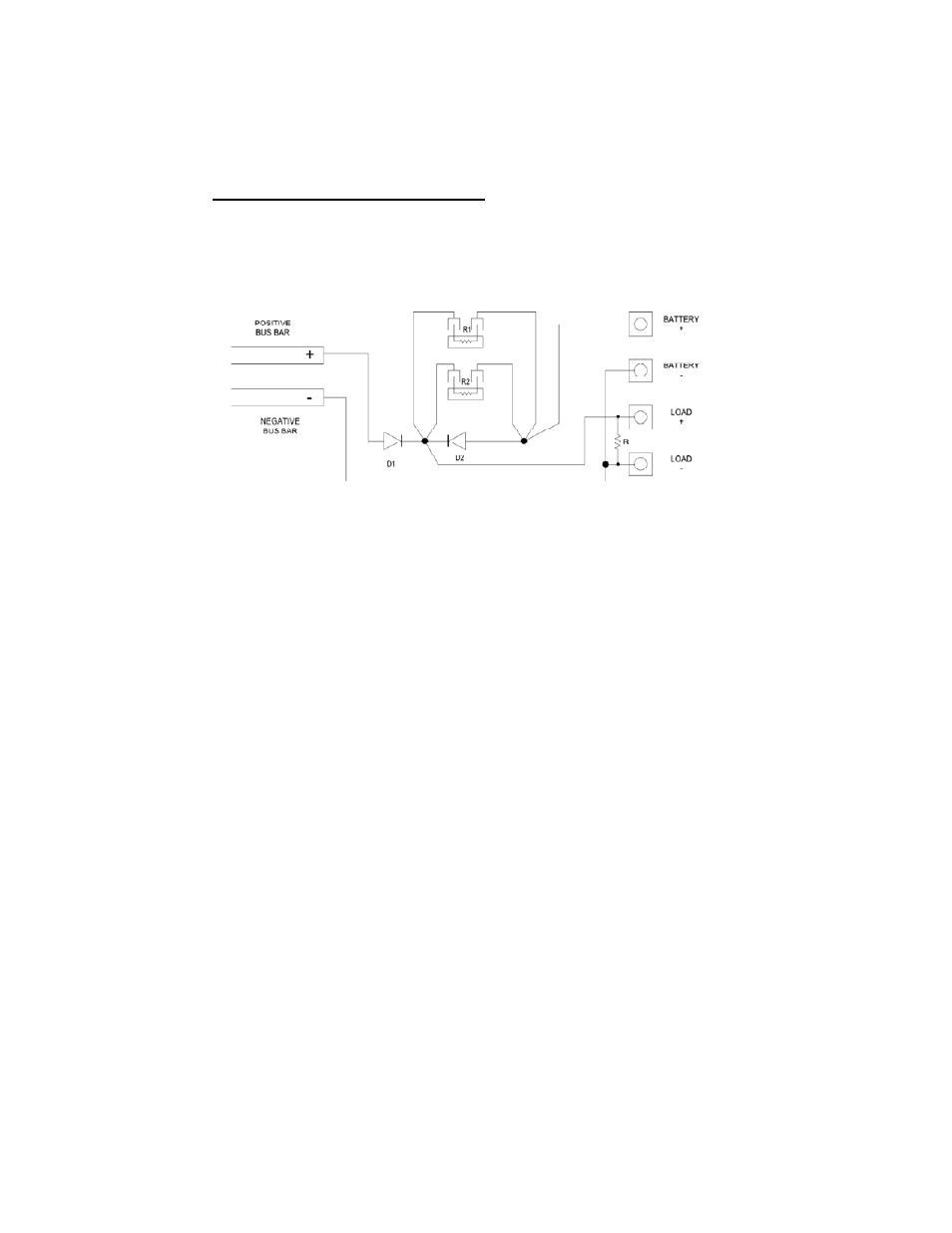
D1, D2
SCHOTTKY DIODE: 30V, 180A
R1
POWER RESISTOR: 1.3 OHM, 35W
R2
POWER RESISTOR: 1.65 OHM, 35W
R
STATIC LOAD RESISTOR: 200 OHM, 5W
FUGURE A.
Please refer to the schematic at fig. A above.
When there is a requirement of un-interrupted D.C. power to the load, an external
battery may be connected at the terminals Battery + and Battery –. When the input
A.C. power is available, the load current is supplied by the power supply through
isolating Schottky Diode D1. At the same time, the battery is charged through resis-
tors R1 & R2. (These resistors will limit the maximum charging current to about 8
Amperes.)