Diagram of 125 hx – AquaStar 125HXNG User Manual
Page 17
17
6 720 606 804
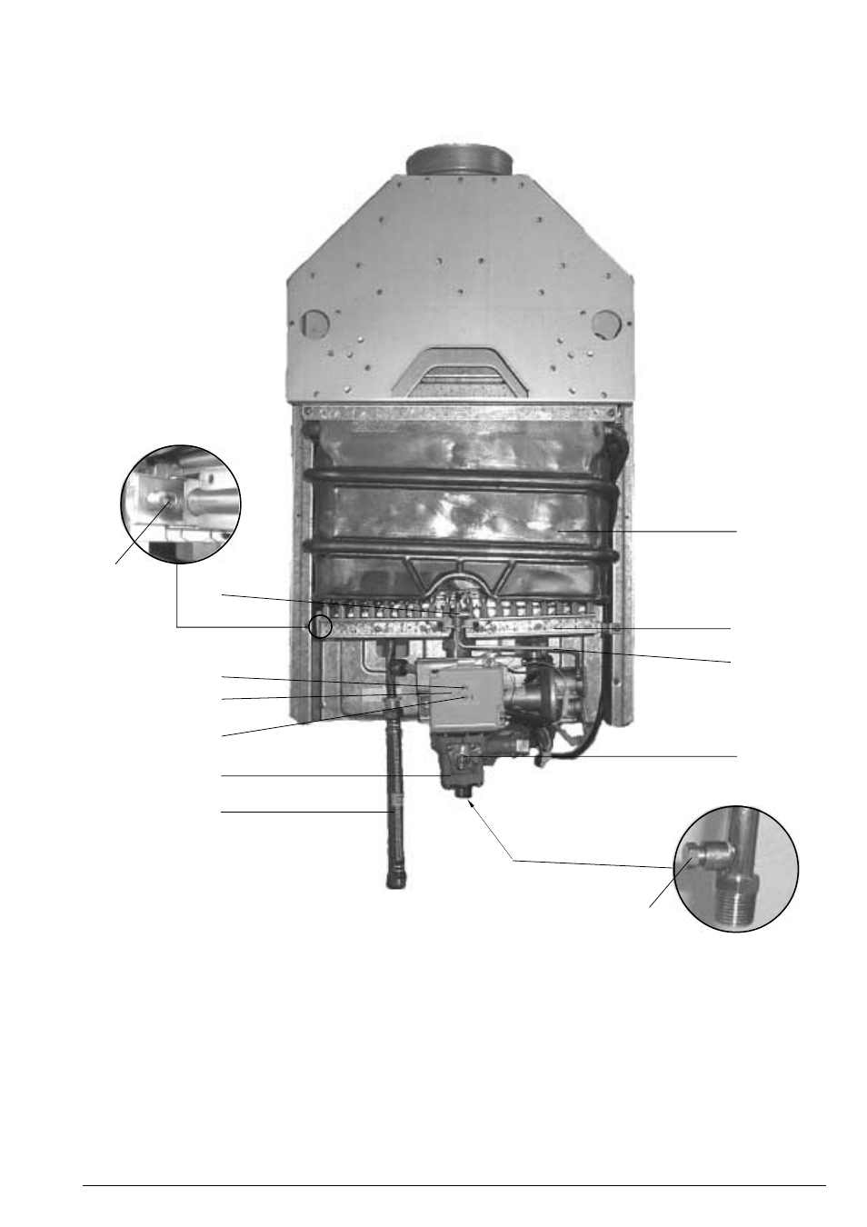
Fig. 14 -
Diagram of 125 HX
1.
Heat exchanger
2.
Pilot assembly
3.
Burner manifold gas
pressure test nipple
4.
Main gas burner
5.
Pilot gas tubing
6.
LED failure indicator
7.
on/off switch
8.
LED operation indicator
9.
Water valve
10.
Temperature adjustment selector
11.
Gas inlet gas pressure test nipple
12.
Hose
3
1
4
10
11
2
9
8
6
7
5
12
6 720 606 804-10.1AL
This manual is related to the following products: