Features, Hardware, Drawing – Matrix Orbital MOP-GL24064A User Manual
Page 4: Interface
3
Features
The Matrix Orbital Parallel display series offers a low cost display solution utilizing an industry standard
communication interface for simple integration into a wide variety of new and existing applications. The
Light Emitting Diode backlight with configurable brightness and voltage controlled contrast allows the
MOP Liquid Crystal Display line to offer a professional display solution for any project.
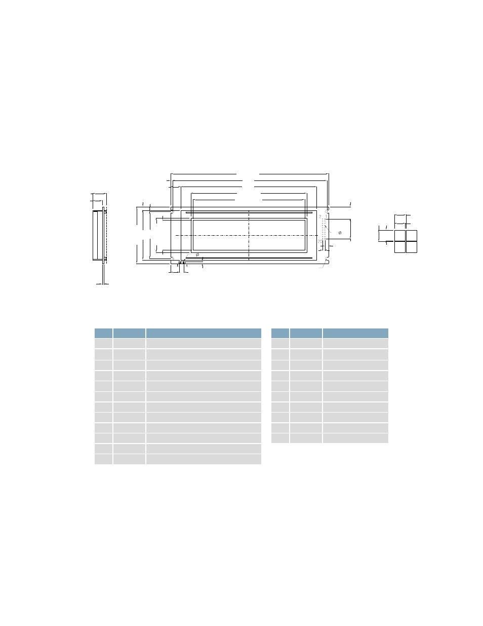
Hardware
Drawing
14.0
65.0±0.5
54.0
56.8
33.88
[A.A
.]
127.16[A.A.]
132.2[V.V.]
3- 1.0
2.5
5.08
10.0
39.2[V.V.]
L
C
4-R1.75
L
C
20- 1.0
4.25
2.54
P2.54X9=22.86
L
C
180.0±0.5
176.0
154.8
5.5
4.1
2.0
11.6
L
C
1.6±0.1
10.9±0.5
16.0[MAX.]
0.53
0.53
0.49
0.49
Figure 1: MOP-GL24064A Mechanical Drawing
Interface
Table 1: Display Control
Pin Symbol
Description
1
FGnd
Frame Ground
2
V
SS
Ground
3
V
DD
Supply Voltage for Logic
4
V
0
Supply Voltage for LCD (Contrast)
5
WR
Write
6
RD
Read
7
CS
Chip Enable
8
C/D
Command/Data
9
NC
No Connect
10
RST
Reset
19
FS
Font Select
20
V
EE
*
Negative Voltage Output
Table 2: Parallel Data and Backlight
Pin Symbol
Description
11
DB0
Data bit 0
12
DB1
Data bit 1
13
DB2
Data bit 2
14
DB3
Data bit 3
15
DB4
Data bit 4
16
DB5
Data bit 5
17
DB6
Data bit 6
18
DB7
Data bit 7
A
LED (+)
Backlight Anode
K
LED (-)
Backlight Cathode
*Note:
Offered on applicable units only