4 general purpose outputs, 5 keypad header – Matrix Orbital GTT38A User Manual
Page 14
GTT38A Hardware Manual
10
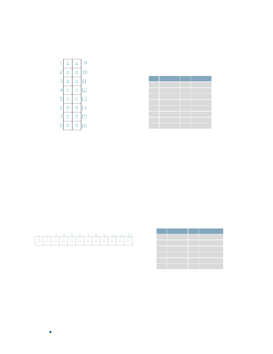
4.4 General Purpose Outputs
A unique feature of the GTT38A is the ability to control relays
*
and other external devices using either
one of six General Purpose Outputs.
Figure 15: GPO Header
Table 9: GPO Pinout
Pin Function Pin Function
1
Gnd
8
Gnd
2
GPO 1
9
Gnd
3
GPO 2
10
Gnd
4
GPO 3
11
Gnd
5
GPO 4
12
Gnd
6
GPO 5
13
Gnd
7
GPO 6
14
Gnd
8
Vcc
16
Gnd
Each can source up to 15mA of current at five volts when on, or sink 15mA at zero volts when off. The
two row, fourteen pin header can be interfaced to a number of female connectors to provide control to
any peripheral devices required.
4.5 Keypad Header
To facilitate user input, the GTT38A provides a Keypad Connector which allows a matrix style keypad of
up to twenty-five keys to be directly connected to the display module. Key presses are generated when
a short is detected between a row and a column. When a key press is generated, a character specific to
that key press is automatically sent on the Tx communication line. If the display module is running in I²C
mode, the key press will remain in the buffer until it is accessed using the display read address.
Figure 16: Keypad Header
Table 10: Keypad Pinout
Pin Function Pin
Function
1
Gnd
7
Column 1
2
Row 1
8
Column 2
3
Row 2
9
Column 3
4
Row 3
10
Column 4
5
Row 4
11
Column 5
6
Row 5
12
Gnd/Vcc
**
The character that is associated with each key press may be altered using the “Assign Key Codes”
command. The straight twelve pin header of the Keypad Interface Connector will interface to a variety
of different devices including the Matrix Orbital KPP4x4 keypad.
*Note:
If connecting a relay, be sure that it is fully clamped using a diode and capacitor in order to absorb any
electro-motive force (EMF) which will be generated.
**Note:
The Ground / +5V pin is toggled by the jumper to the top right of the keypad connector. Jump pads 1 & 2
for +5V or 2 & 3 for GND.