Aalborg SMV Series User Manual
Page 10
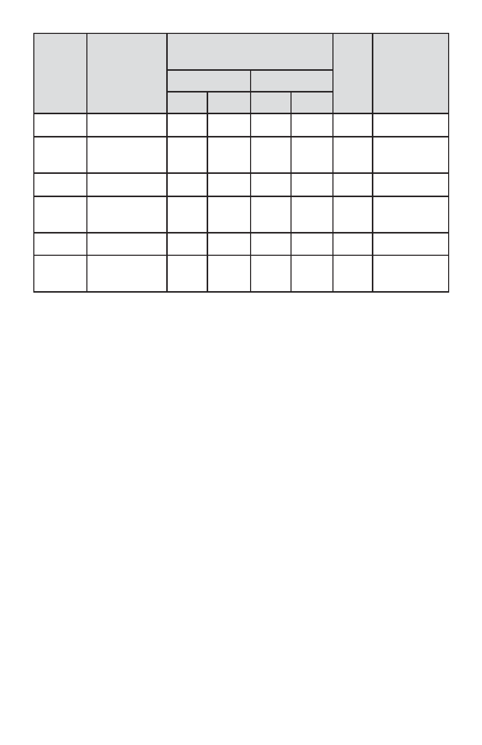
TABLE I FLOW CONFIGURATIONS
4.
OPERATING INSTRUCTIONS
The SMV motorized valve requires a +12VDC power supply with a minimum
current rating of 800 mA. The operating power and valve control signals are
supplied via the 9-pin "D" connector located at the side of the valve.
The SMV motorized valve has three modes of operation: Valve Active
(Auto), Valve OFF Control and Valve Purge (Open).
4.1 Valve Active (Auto)
For normal operating in Auto mode the motorized valve requires at least two
control signals:
l Direction (12Vdc CMOS compatible logic level, pin 8 on the 9-pin "D" connector)
l Speed (0-2.5 VDC analog signal, pin 4 on the 9-pin "D" connector)
When direction is LOW (GND) valve goes down (closes), when direction is
HIGH valve goes up (opens). The "speed" voltage on pin 4 determines how
quickly the valve will operate. The signal amplitude for "speed" control signal
must remain within the limits of 0 to +2.5 VDC. The 2.5 Vdc input signal cor-
responds to approximately 250 steps per second. With resolution of the step-
ping motor of 0.00025"/step it results in a maximum speed about 0.0625"/sec.
6
MODEL
NUMBERS CONSTRUCTION
MAXIMUM FLOW RATE
(at 20 psi diff. pressure, 70
F
F)
Cv
CONNECTIONS
AIR
WATER
sL/min
scfh
L/min
GPM
SMV20-A
Aluminum
200
424
5.6
1.48
0.336
3/8”
SMV20-S
316 stainless
steel/PTFE
200
424
5.6
1.48
0.336
3/8”
SMV30-A
Aluminum
500
1060
14.2
3.75
0.855
1/2”
SMV30-S
316 stainless
steel/PTFE
500
1060
14.2
3.75
0.855
1/2”
SMV40-A
Aluminum
1000
2119
28
7.4
1.735
3/4” FNPT
SMV40-S
316 stainless
steel/PTFE
1000
2119
28
7.4
1.735
3/4” FNPT