Aalborg OSS-2 Optical User Manual
Page 5
2
3.
INSTALLATION
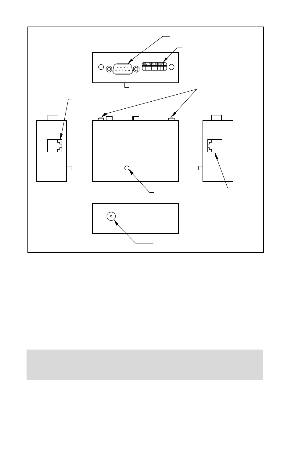
3.1 Electrical
Connections
The Optical Sensor Switch requires a +12VDC power supply with a minimum
current rating of 250 mA. Operating power and alarm reset signals are supplied
via the 9-pin AD@ connector located at the side of the Optical Sensor Switch.
Alternatively power can be connected via the DC power jack on the bottom side
of the unit. If you are using your own power supply, be sure that the voltage
level is between +12 and +15 Vdc.
POWER JACK
RESET BUTTON
ALARM CONFIGURATOR
9-PIN D-CONNECTOR
LED INDICATORS
PHONE JACK 1
PHONE JACK 2
SUPPLYING DC POWER TO THE POWER JACK AND THE “D” CONNECTOR AT
THE SAME TIME WILL DAMAGE THE METER. DC POWER JACK POLARITY IS
CENTER POSITIVE.
ƽ
The DIP switch, located near 9-pin D-connector can be used to set up custom
settings separately for High and Low alarm.