Aalborg DFC Digital User Manual
Page 19
priate relative correction factor should be recalculated see section (9).
It is standard practice to calibrate Mass Flow Meters/Controllers with dry nitrogen
gas at 70
F
F (21.1EC), 20 psig (1.4 bars) [25 psig (1.7 bars) for DFC46] inlet pres-
sure and 0 psig (0 bar) outlet pressure. It is best to calibrate the DFC transducers
to actual operating conditions. Specific gas calibrations of non-toxic and non-cor-
rosive gases are available at specific conditions. Please contact your distributor or
Aalborg
7 for a price quotation.
It is recommended that a flow calibrator of at least four times better collective accu-
racy than that of the Mass Flow Controller to be calibrated be used. Equipment
required for calibration includes a flow calibration standard and a certified high
sensitivity multimeter (which together have a collective accuracy of +0.25% or bet-
ter), an insulated (plastic) screwdriver, a flow regulator (example: metering needle
valve) installed upstream from the Mass Flow Controller and a pressure regulated
source of dry filtered nitrogen gas (or other suitable reference gas).
The gas and ambient temperature, as well as inlet and outlet pressure conditions
should be set up in accordance with actual operating conditions.
7.2
Calibration of DFC Mass Flow Controllers
All adjustments to the DFC calibration and control loop tuning are accomplished
using the RS485 (or optional RS232) interface in conjunction with setup and cal-
ibration software available from Aalborg
7. The sensor zero is automatically
adjusted internally whenever the control valve is fully closed (set point less than
2% of full scale) and the unit is warmed up.
DFC Mass Flow Meters may be field recalibrated/checked using the setup and
calibration program for the same range they were originally factory calibrated for.
Flow range changes may require a different Restrictor Flow Element (RFE).
Additionally, a different Solenoid Valve Orifice for the DFC Mass Flow Controller
(see Table VI) may also be required. Consult your distributor or Aalborg
7 for more
information.
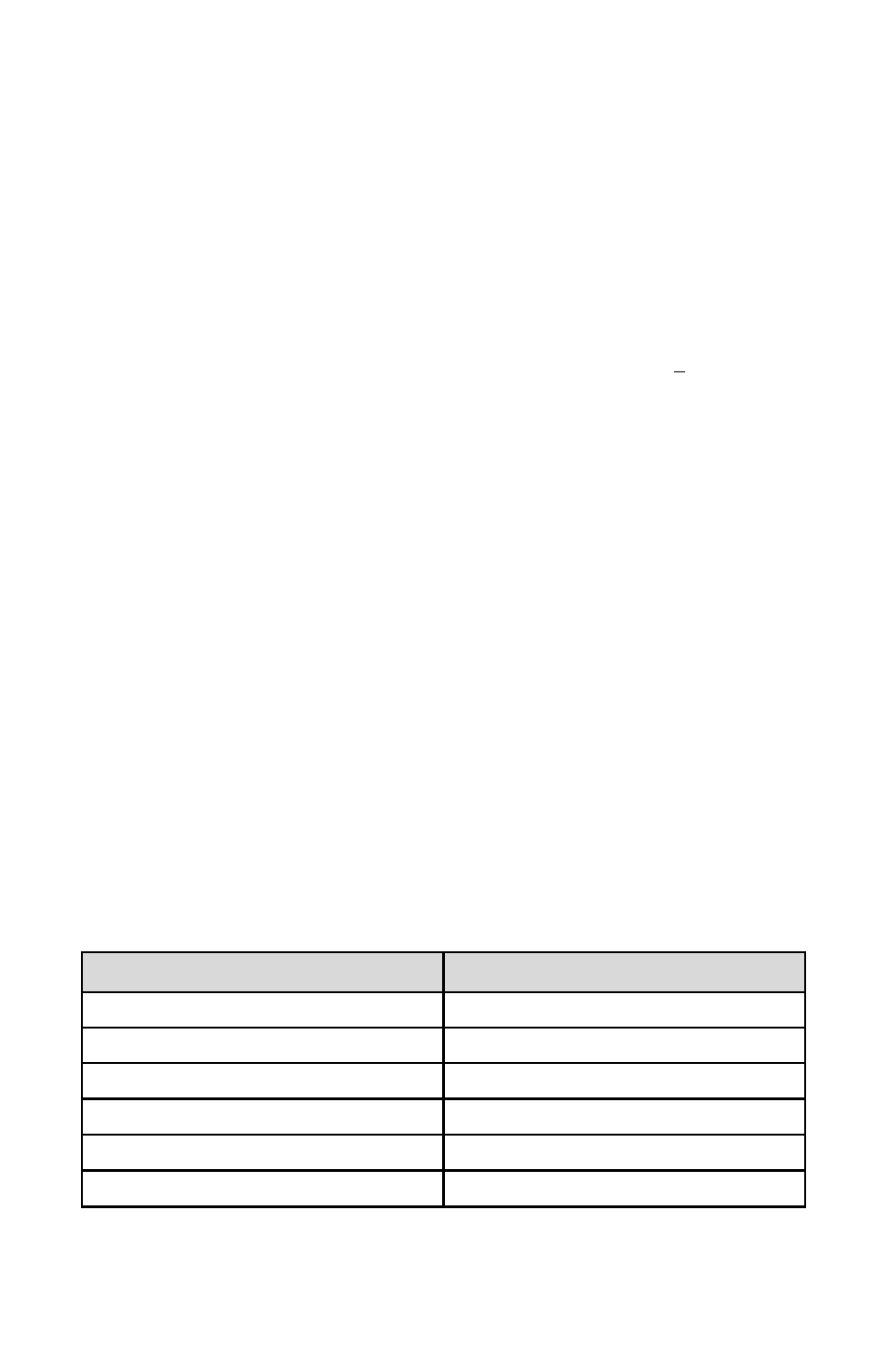
TABLE VI DFC SOLENOID VALVE ORIFICE SELECTION TABLE
16
ORIFICE PART NUMBER
FLOW RATE [N
2
]
OR.020
10 to 1000 sccm
OR.040
1 to 5 slpm
OR.055
5 to 10 slpm
OR.063
10 to 15 slpm
OR.094
20 to 50 slpm
OR.125
50 to 100 slpm