Nilfisk-ALTO R 680 B User Manual
Page 91
USER MANUAL
ENGLISH
1463516000(1)2008-05 A
FLOORTEC R 680 B
29
Disconnect the battery connector (25) and connect it to the external battery charger.
6.
Connect the battery charger to the electrical system and charge the batteries.
7.
After charging, disconnect the battery charger from the electrical mains and from the connector (25).
8.
Check the electrolyte level and close all caps (24).
9.
Connect the battery connector (25) to the machine.
10.
Remove the support rod (36) and close the hood (22). The machine is ready to be used.
11.
FUSE CHECK/REPLACEMENT/RESET
Drive the machine on a level ground and engage the parking brake with the pedal (75) and the lever (68).
1.
Turn the ignition key (67) to “0”.
2.
Open the hood (22) and fasten it with the support rod (36).
3.
Disconnect the battery connector (25).
4.
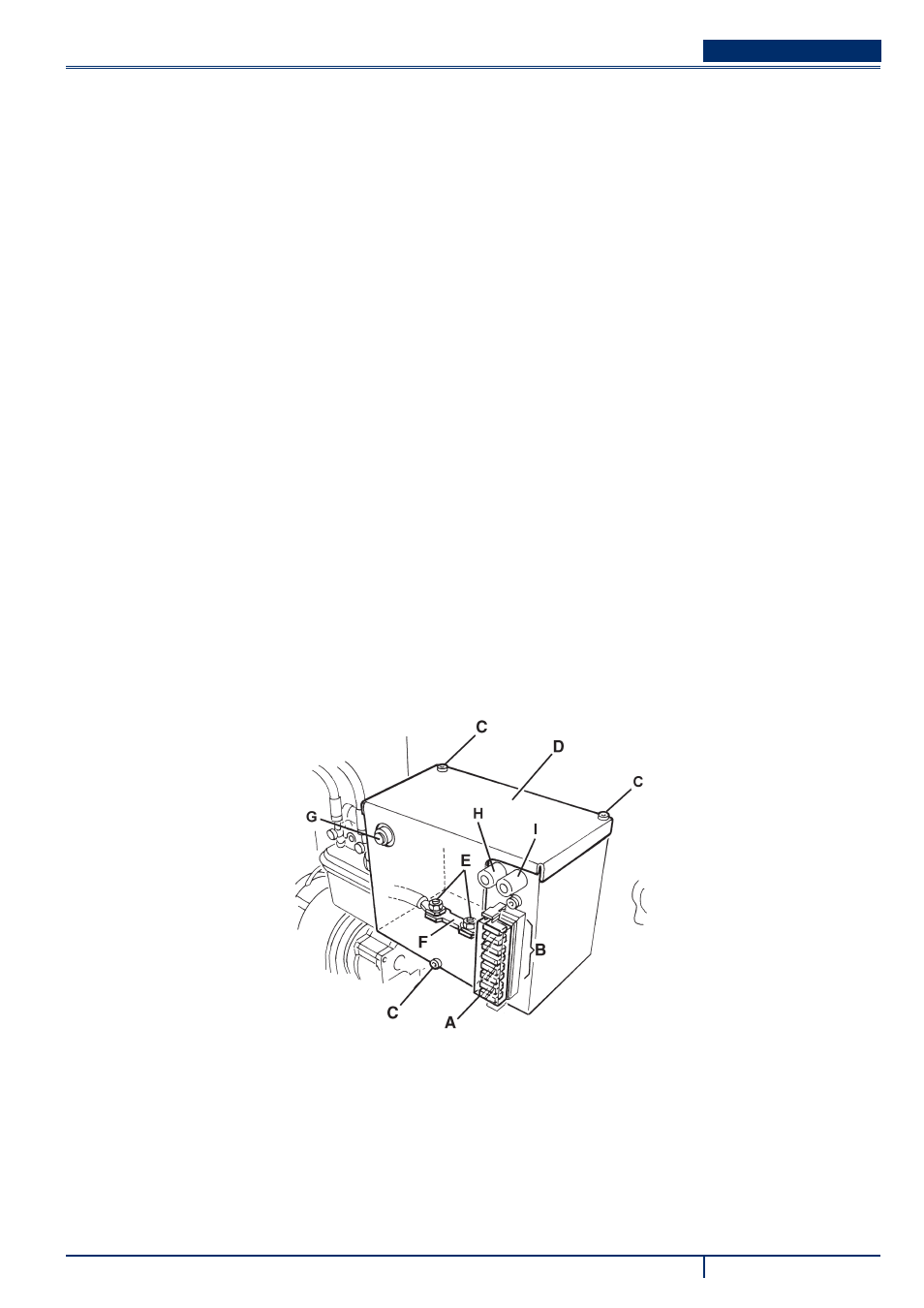
Lamellar fuse check/replacement
Remove the cover (A, Fig. 28) and mark the positions of the fuses shown on the adhesive.
5.
Check/replace the relevant fuse among the following (B):
6.
F1 fuse (30 A): Key circuit
•
F2 fuse (30 A): Filter shaker
•
F3 fuse (30 A): Vacuum system
•
F4 fuse (30 A): Hydraulic pump
•
F5 fuse (10 A): Flashing light (optional)
•
F6 fuse (10 A): Working light (optional)
•
F7 fuse (10 A): Hopper actuator
•
F8 fuse (30 A): Spare fuse
•
Main fuse check/replacement
Remove the screws (C, Fig. 28), then remove the cover (D).
7.
Remove the nuts (E).
8.
Check/replace the main fuse F0 (150 A) (F)
9.
Circuit breaker check
Check for deactivation of one of the following fuses, then reset it after the relevant motor has cooled down:
10.
FA fuse (H, Fig. 28): Right side broom motor circuit breaker
•
FB fuse (I): Left side broom motor circuit breaker (optional)
•
FC fuse (G): Main broom motor circuit breaker
•
Assembly
Assemble the components in the reverse order of disassembly.
11.
S311447
Figure 28