10 operation – Burr King Oregon Model 760 With Mower Blade User Manual
Page 10
10
Operation
ALIGNING IDLER WHEELS
When idler wheels are removed and/or replaced they
must be installed such that they are in proper alignment.
Failure to properly align the idler wheels will result in
premature failure of the wheels. Premature failure will
be evidenced by outer diameters being excessively worn
such that the wheels lose their factory crown, wear to a
truncated form, or become out of balance. Misalignment
results in wear that is analogous to front tire wear when the
front steering mechanism of an automobile is misaligned.
The upper idler equates to the front wheels of the car. If
either idler wheel is misaligned to each other or to the
contact wheel, excessive and irregular wear will occur.
The upper and rear idler wheels must operate in the
same plane. This means that when they are correctly
aligned a plane passing through the radial center of the
upper wheel will exactly pass through the radial center
of the rear wheel. Machines are shipped from the factory
with wheels of the same width. Currently, model 760
machines are shipped with wheels that are 1.5 inches
wide. The model 760 also has available contact wheels
0.5, and 2.0 inches wide, along with corresponding
belts. Contact your OREGON® distributor for details.
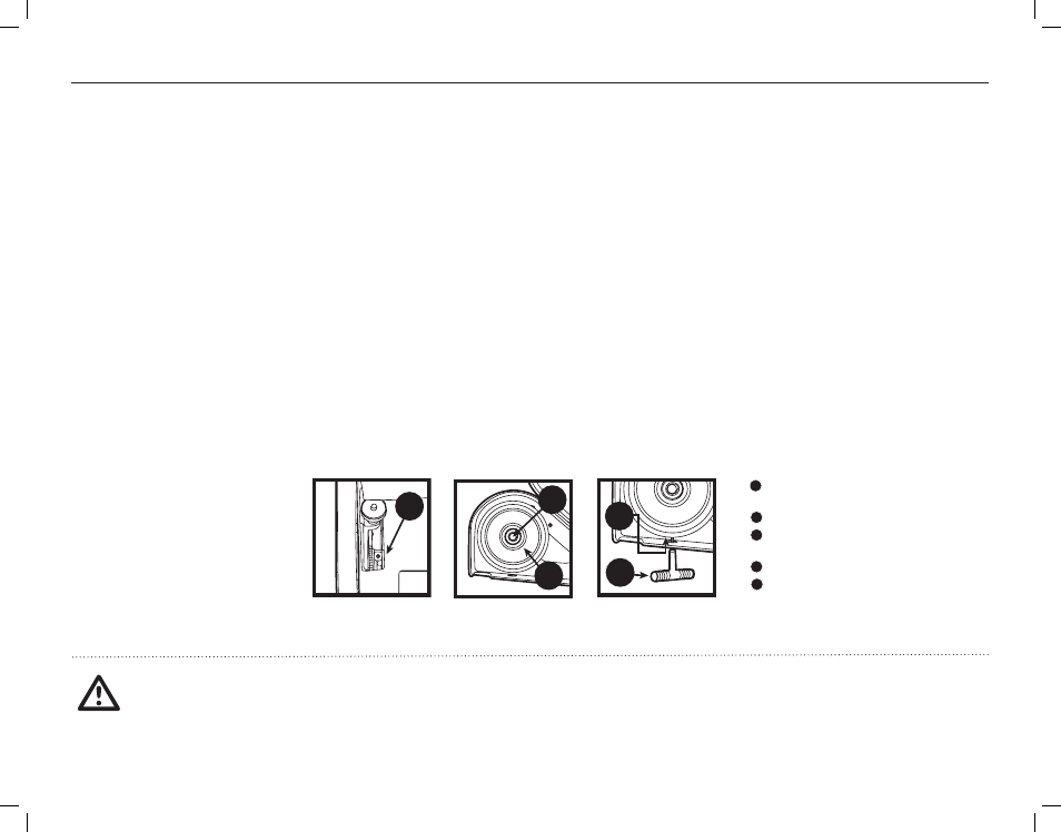
1. Disconnect electric power and
remove the abrasive belt.
2. Install the rear idler such that its inside
bearing surface is approximately 0.06 inches
out from the wheel support. Secure the
wheel with locking set screw. (Figure 11)
3. Install the upper wheel such that its inner
bearing surface is approximately 0.06 inches
out from its bearing support. Secure the
wheel with locking set screw. (Figure 12)
4. Loosen the retaining nut that locks the upper idler
wheel adjusting screw. (Figure 13) Using screw
adjust the upper idler wheel until a straight line
representing the plane passing through the center
of the upper idler exactly passes through the
center of the contact wheel. This line represents
the center of belt travel. Note: make certain that
the bearing support is against the screw end.
5. Project a line from the upper idler outside rim to
the outside rim of the rear idler. Adjust the tracking
adjustment knob until the wheels are exactly
planar. That is, their radial centers are aligned.
6. Repeat step 3 and 4 until both conditions
are satisfied. That is, the upper and rear
idlers are aligned to each other and both
wheels are aligned to the contact wheel.
7. Tighten the locking nut on the upper
idler wheel adjusting screw.
8. Install a new abrasive belt. Roll the belt manually
to assure that it will maintain coarse tracking. If
the belt does not track manually, repeat the prior
steps until it does. If after repeating these steps the
belt still will not track, the machine requires other
maintenance and/or one or both idler wheels require
replacing. The wheels should be replaced in pairs.
9. Apply electric power to the machine and verify
that the tracking adjustment knob (Item 9,
pg. 5) will sweep the belt across the face of
the contact wheel. At least ½-inch adjustment in
both directions from center should be possible.
WARNING:
NEVER PERFORM MAINTENANCE OR
ADJUSTMENTS ON YOUR MODEL 760 WITHOUT
FIRST DISCONNECTING THE MACHINE FROM ITS
SOURCE OF ELECTRIC POWER.
FAILURE TO OBSERVE THIS WARNING MAY LEAD TO
SERIOUS PERSONAL INJURY.
FIGURE 11
FIGURE 12
FIGURE 13
1
2
3
5
4
LOCKING SET SCREW,
REAR IDLER WHEEL
UPPER WHEEL
LOCKING SET SCREW,
UPPER IDLER WHEEL
RETAINING NUT, UPPER IDLER WHEEL
5/32" ALLEN WRENCH
1
6
7
8
9
12 13
15
10 11
14
16 17 18 19 20
4
3
2
5
1
6
7
8
9
12 13
15
10 11
14
16 17 18 19 20
4
3
2
5
1
6
7
8
9
12 13
15
10 11
14
16 17 18 19 20
4
3
2
5
1
6
7
8
9
12 13
15
10 11
14
16 17 18 19 20
4
3
2
5
1
6
7
8
9
12 13
15
10 11
14
16 17 18 19 20
4
3
2
5