Repeater operation, Controls and functions, Transceiver operation (analog mode only) – Kenwood TKR-D810E User Manual
Page 3: Rear panel, Front panel, Receive, Transmit
2
REPEATER OPERATION
Note:
◆
Please consult your dealer for programming the repeater.
◆
After switching the power on, the CH/STATUS display blinks for
approximately 30 seconds, until the internal circuit stabilizes. Wait
until the display remains lit, before operating.
When power is applied to the unit, the POWER indicator lights:
・
Green when using the DC jack.
The BUSY indicator lights green while receiving a signal and the
TX indicator lights red while transmitting.
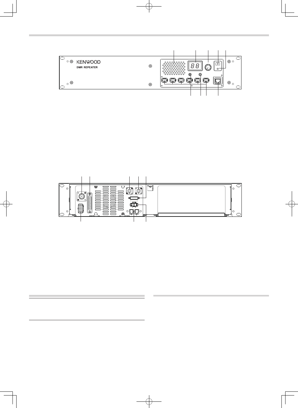
■
Rear Panel
a
TX OUT jack
Connect a TX antenna or a duplexer to this receptacle.
b
CONTROL I/O jack
Connect a repeater controller or a remote panel to this
DB-25 interface.
c
REF IN jack
This jack is currently not used.
d
RX IN jack
Connect an RX antenna or a duplexer to this BNC
receptacle.
CONTROLS AND FUNCTIONS
■
Front Panel
e
FUSE
Insert 15 A blade fuse into this fuse holder.
f
DC 13.2V jack
Connect a 13.2 V DC power supply to this jack.
g
N SYNC 1 / 2 jack
This jack is currently not used. Future functions include
connecting another repeater or optional device.
h
TEST/SPKR jack
Test input/output jack. Connect an external speaker to this
jack.
TRANSCEIVER OPERATION (Analog mode only)
■
Receive
Adjust the volume to your desired level. You may need to
readjust the volume if you are having interference while
receiving a message from your dispatcher or another member
in your fleet.
The BUSY indicator lights green while a signal is being
received.
■
Transmit
1 Listen to the channel before transmitting, to make sure it is
not being used.
2 Press the microphone PTT switch, then speak in your
normal speaking voice.
The TX indicator lights red while transmitting.
3 When you finish speaking, release the PTT switch.
a
Speaker
b
CH/STATUS Display
Two 7-segment digits display the channel number, name,
or status.
c
VOLUME control
Rotate to adjust the audio.
d
POWER switch
e
POWER indicator
Lights green when power is supplied to the DC 13.2V jack.
f
MIC jack
Connect a microphone to this 8-pin modular jack.
g
Programmable Function keys
Press these keys to activate their programmable functions.
h
BUSY indicator
Lights green while a signal is being received.
i
TX indicator
Lights red while transmitting.
a
b
d e
f
g
h
i
c
CH/STATUS
VOLUME
BUSY
TX
POWER
MIC
a b
d e
f
g
c
h
N S Y N C
REF
IN
RX
IN
TX OUT
CONTROL
I / O
TEST/SPKR
DC 13.2V
FUSE 15A