Main channel frequencies – Audiovox GMRS672 User Manual
Page 2
10
VOX Selection Mode
This option enables you to have hands-free conversation.When using the
internal microphone/speaker, your voice or the signal is detected and the
radio transmits and receives automatically.Your voice or nearby sound
is detected and the radio transmits without the need to press the PTT
buttton.
To set the radio for VOX operation:
- From GMRS/FRS standby mode, press and hold the MODE button
for 2 seconds, or until the VOX icon appears on the display.
- To terminate VOX operation, press and hold the MODE button for at
least 2 seconds; the VOX indication will disappear.
Channel Scan Operation
This feature allows you to monitor all channels automatically for valid
signals. While scanning, you can transmit and receive. When a signal is
received, the scan is interrupted and will return to scan mode approxi-
mately 5 seconds after reception is terminated.
NOTE:
While the scan function is active, the MODE/VOX button
will be inoperative. The scan mode will reduce the overall
battery life since the battery save function is overridden.
To enable the channel scan mode:
- From GMRS/FRS standby mode, momentarily press the Power (S)
Button; (SCAN) will appear on the LCD display.
- The radio will display each channel (1-22) in ascending order as the
scan mode operates to find an active main channel.
- If the unit doesn’t find any signals and you want to transmit, press
the PTT button to return to home channel operation. The transceiver
will automatically resume scanning approximately 5 seconds after
the communication is completed.
- If there is no activity and you want to leave the scan mode, press the
S button momentarily and the unit will return to normal operation;
the SCAN icon will disappear from the LCD display.
Button Beep (Key Tone)
This feature allows the transceiver to sound a confirmation tone whenever
the following keys are pressed: Power On/Off/SCAN Button, Up/Down But-
tons and MODE Button. This feature is always on.
Roger Beep Tone
The Roger Beep is a tone which is automatically transmitted whenever the
PTT button is released and the tone is enabled. This tone alerts the re-
ceiving party that the transmission has been terminated intentionally
To enable and disable the Roger Beep tone:
- From GMRS/FRS standby mode, press the MODE Button 2 times
until the flashing Roger Beep icon ( ) appears with on or oF.
- Press the Up or Down Button to select the tone on or off as desired.
- When enabled, the tone icon ( ) appears steady on the display.
- Press the PTT button momentarily to confirm selection.
Battery Alert
When the battery icon (
) blinks on/off at 7-second intervals, as shown
on the LCD panel, recharge or install fresh batteries.
NOTES FOR GOOD COMMUNICATION
1 . The 22 channels of the GMRS672 are shared on a ‘take turns’
basis. This means other groups may be talking on any of the chan-
nels. A common code of ethics/courtesy is to switch to another
vacant channel and not to attempt to talk over someone who is already
using the channel you first selected.
2. The GMRS672 has been designed to maximize performance and
improve transmission range in the field. To avoid interference, it is
recommended that you do not use the units closer than 5 feet apart.
3. For best transmission results, always keep your mouth about 2-3
inches from the microphone (5) and speak slowly in a normal voice.
4. To increase battery life, use the SCAN feature sparingly. This
feature will reduce operating time considerably.
11
12
Warning
• Do not operate the transceiver unless you are licensed to do so.
• Remove the batteries from the transceiver if it is not expected to be used
for long periods. This will eliminate the possibility of chemicals leaking
from the batteries and corroding the transceiver.
• Avoid exposing the transceiver to water or extremes of temperature.
• Do not use this device in or near a mining facility, which uses remotely
triggered explosives or in areas labeled “Blasting Area”. Premature or
accidental detonation may result.
• Do not attempt to modify or in any way increase the output of this
transceiver. Its output is designed to meet the legal limits set by the FCC.
• Do not use this device or change its batteries in potentially explosive
atmospheres as sparks in such areas could result in an explosion.
• Turn your transceiver off wherever posted notices restrict the use of
radios or cellular telephones. Facilities such as hospitals may use equip-
ment that is sensitive to RF energy.
• Turn your transceiver off on board aircraft when requested to do so.
• Do not place your radio in front of a vehicle’s air-bag. If the air-bag
deploys, it could propel the transceiver like a projectile causing bodily
injury.
General
Frequency Range:
Channels 1 through 7 are
shared with FRS radios.
Refer to frequency chart on next page.
Channels 8 through 14 are
FRS only.
Refer to frequency chart on next page.
Channels 15 through 22 are
GMRS only.
Refer to frequency chart on next page.
Channel Spacing
12.5kHz
Dimensions (W x H x D)
1.96” W x 3.31” H x 1.10” D
(Without Antenna)
(49.8 mm x 84.0 mm x 28.0 mm)
Power Supply
Power Source
Alkaline Batteries, AAA (3), 4.5 VDC
Operating Time
30 hours
(Transmit: Receive: Standby)
(5: 5: 90 ratio)
(Based on alkaline batteries)
Receiver
Useable Sensitivity
>-119 dBm
Maximum Audio Output Power
> 0.25 Watt maximum (8 Ohm )
Modulation Distortion
< 5% (1 kHz 70%)
Transmitter
RF Output Power
0.5 Watt maximum
Maximum Deviation
+/- 2.5 kHz
Modulation Distortion
< 5% (1 kHz 70%)
14
Technical Specifications:
15
90 DAY LIMITED WARRANTY
AUDIOVOX CORPORATION, 150 MARCUS BLVD., HAUPPAUGE, NEW YORK 11788
1-800-290-6650
128-5385C
Applies to Audiovox Family Radio and General Mobile Service Products.
AUDIOVOX CORPORATION (the Company) warrants to the original retail purchaser of this
product that should this product or any part thereof, under normal use and conditions, be proven
defective in material or workmanship within 90 days from the date of original purchase, such
defect(s) will be repaired or replaced with new or reconditioned product (at the Company's option)
without charge for parts and repair labor.
To obtain repair or replacement within the terms of this Warranty, the product is to be delivered
with proof of warranty coverage (e.g. dated bill of sale), specification of defect(s),
transportation prepaid, to the warranty center at the address shown below.
The Company disclaims liability for communications range of this product.
This Warranty does not apply to any product or part thereof which, in the opinion of the
Company, has suffered or been damaged through alteration, improper installation, mishan-
dling, misuse, neglect, accident, or by removal or defacement of the factory serial number/
bar code label(s). THE EXTENT OF THE COMPANY'S LIABILITY UNDER THIS WARRANTY
IS LIMITED TO THE REPAIR OR REPLACEMENT PROVIDED ABOVE AND, IN NO EVENT,
SHALL THE COMPANY'S LIABILITY EXCEED THE PURCHASE PRICE PAID BY
PURCHASER FOR THE PRODUCT.
This Warranty is in lieu of all other express warranties or liabilities. ANY IMPLIED
WARRANTIES, INCLUDING ANY IMPLIED WARRANTY OF MERCHANTABILITY, SHALL BE
LIMITED TO THE DURATION OF THIS WRITTEN WARRANTY. ANY ACTION FOR BREACH
OF ANY WARRANTY HEREUNDER INCLUDING ANY IMPLIED WARRANTY OF MER-
CHANTABILITY MUST BE BROUGHT WITHIN A PERIOD OF 12 MONTHS FROM DATE OF
ORIGINAL PURCHASE. IN NO CASE SHALL THE COMPANY BE LIABLE FOR ANY
CONSEQUENTIAL OR INCIDENTAL DAMAGES FOR BREACH OF THIS OR ANY OTHER
WARRANTY, EXPRESS OR IMPLIED, WHATSOEVER. No person or representative is
authorized to assume for the Company any liability other than expressed herein in connection with
the sale of this product.
Some states do not allow limitations on how long an implied warranty lasts or the exclusion
or limitation of incidental or consequential damage so the above limitations or exclusions may
not apply to you. This Warranty gives you specific legal rights and you may also have other
rights which vary from state to state.
Troubleshooting
13
Weak or no
Weak batteries
Replace batteries
signal received
Channel
Adjust the transceiver’s
not set the same
settings to match those
as target transceiver
settings of the target
transceiver
Volume level too low
Increase volume level
PTT Button inadvertently
Release PTT Button
depressed
Excessive radio interference
Change to a different
on a particular channel
channel
Obstruction of radio signal
Avoid operating in or near
large buildings or vehicles
Unit beeps, but
Batteries extremely
Replace batteries
will not function
discharged
when turned on
Reception of
Interference from
Turn the devices off or move
unwanted
electronic devices such
farther away from them.
signals
as computers or TVs
Problem
Possible cause
Correction
No transmission
Weak batteries
Replace batteries
while pressing
Incorrect battery polarity
Install the batteries using
the PTT Button
the directions for correct
battery installation.
This transceiver complies with FCC regulations for use in the United
States of America. Use in other countries may be prohibited or restricted
by local regulation. Please check with the local regulating agency be-
fore using this device outside the United States of America.
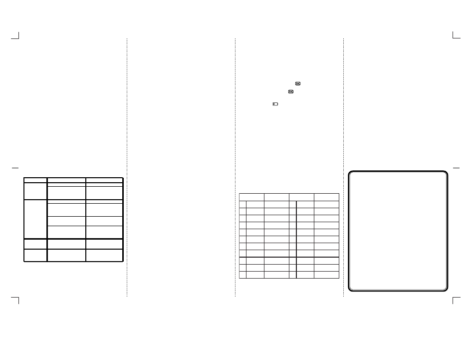
Main Channel Frequencies:
NOTE: Channels 1 through 7 are shared with FRS radios.
Channels 8 through 14 are FRS only.
Channels 15 through 22 are GMRS only.
CHANNEL/TYPE
1
2
3
4
5
6
7
8
9
10
11
FREQ (MHz)
462.5625
462.5875
462.6125
462.6375
462.6625
462.6875
462.7125
467.5625
467.5875
467.6125
GMRS/FRS
GMRS/FRS
GMRS/FRS
GMRS/FRS
GMRS/FRS
GMRS/FRS
GMRS/FRS
FRS
FRS
FRS
FRS
CHANNEL/TYPE
FREQ (MHz)
467.6625
467.6875
467.7125
462.5500
462.5750
462.6000
462.6250
462.6500
462.6750
462.7000
FRS
FRS
FRS
GMRS
GMRS
GMRS
GMRS
GMRS
GMRS
GMRS
GMRS
12
13
14
22
21
20
19
18
17
16
15
467.6375
462.7250
9
Operating Modes and Features
GRMS/FRS Operation:
- Press and hold the Power On/Off button for 2 seconds to turn on
power.
- Press the MODE button so the Channel number flashes.
- Select the desired channel with the Up (10) and Down (11) Buttons.
When receiving a call, the RX icon appears to indicate an incoming
call.
- Press and hold the PTT button (3) to transmit, then speak into the
microphone clearly and slowly.
- Release PTT Button (3) to receive.
- Communication can only be accomplished when the channel of at
least two parties are the same.
Channel Selection
In order to communicate with other GMRS/FRS units, both the transmit-
ting and receiving party must be on the same frequency.
The GMRS672 has 22 channels (frequencies) indicated by the large
digits on the LCD display panel. Channels 1 through 7 are the shared
GMRS/FRS channels. Channels 8-14 are FRS only channels, while chan-
nels 15-22 are assigned GMRS only channels. Communication with
Audiovox GMRS/FRS and compatible units is possible on these 22 chan-
nels.
To change the channel:
- From GMRS/FRS standby mode, press the MODE button (9) once;
the channel number flashes.
- Press the Up Button (10) briefly to move to the next higher main chan-
nel number.
- Press the Down Button (11) briefly to move to the next lower main
channel number.