Raid hba, Hardware configuration 5. building up procedures, Overview 2. package checklist 3. panel layout – HighPoint NA333TB User Manual
Page 2
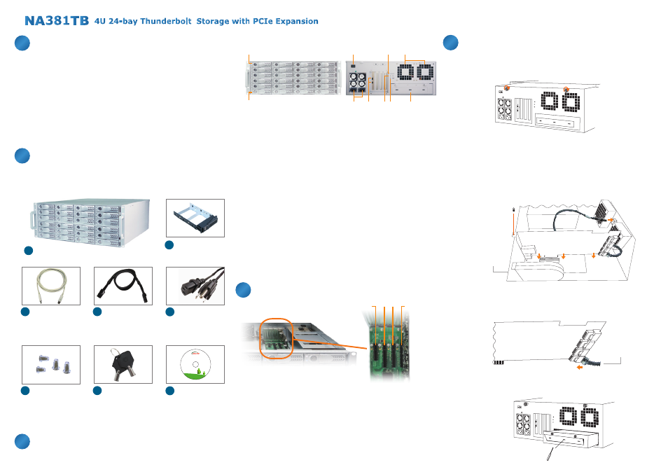
Before installing this unit, verify the package contains the following items.
1. HDD Power LED
。
White - Power On Indicator
2. HDD Status LED
。
Flash Blue - HDD Accessing Indicator, Red - HDD Failure Indicator
3. PSU power button
。
“I” for enable, “0” for disable
4. Power cord receptacles
5. Thunderbolt connectors
。
Connecting Thunderbolt
TM
cables to host and downstream device
6. Mute Button
。
Reset for buzzer beeping
7. Fan Status LED
。
Normal – Green
。
Failure – Red (too slow RPM or stop)
8. Temperature LED
。
Normal – Green
。
Over 50°C – Red
9. Cooling fans
10. Swappable integrated plate drawer for
Mac mini/Mac mini Server
4.
Hardware Configuration
5.
Building Up Procedures
Power cord x 2
E
Thunderbolt
TM
cable
D
(2 meters) x 1
C
HDD Tray x 24
(installed in chassis)
B
Notify your sales representative if any of the above items is missing or
damaged.
Based on the latest Thunderbolt
TM
technology and PCIe architecture,
the creative, innovative design of NA381TB features RAID level protection
and high-performance with PCIe expansion ability to Mac mini or Mac
mini Server through the blazing-fast Thunderbolt
TM
interface. Moreover,
the Thunderbolt
TM
NA381TB enclosure accommodates SAS/SATA
6G/3Gbps hard drives and can be installed with FC/10GbE network card
for high-speed SAN application.
1. Place NA381TB chassis on a level surface of a stable table.
2. Open the chassis by removing the top cover.
3. Three PCIe slots on rear of NA381TB are covered by removable
L-shape metal brackets. Unscrew the screw of the removable
L-shape metal bracket, and the PCIe slots are ready for installation
of PCIe cards.
4. Install one SAS/SATA RAID controller card and other PCIe cards into
proper PCIe slots of NA381TB and tighten them with screws on the
brackets of the PCIe cards.
5. Connect the cable between the topmost mini-SAS connector on
backplane and the mini-SAS connector Channel 1~4 on RAID card,
and connect the rest cables subsequently to the bottommost one on
backplane and Channel 21~24 on RAID card.
6. Loosen the two thumbscrews on swappable integrated plate drawer,
and pull it out. Use a tool to bend the metal board on plate drawer to
separate the metal board from drawer.
1.
Overview
2.
Package Checklist
3.
Panel Layout
1
2
Key for HDD tray
x 2
G
Manual CD-ROM
x 1
H
HDD mounting
screw x 96
F
Internal mini-SAS
(SFF-8087) to
mini-SAS (SFF-8087)
cable 30 cm x 6
Green IT makes
Green Earth
NetStor Technology Co. Ltd.
www.netstor.com.tw
Enclosure x 1
A
3
9
6
5
7 8
4
10
slot 4
slot 3 slot 2
slot 1
Slot 1 : Thunderbolt
TM
target card
(already fixed in the chassis)
Slot 2 : PCIe x8 slot (RAID controller card is
recommended to be installed in this slot because
it is closest to the connectors of backplane)
Slot 3 : PCIe x8 slot (Supports PCIe card x1/x4/x8)
Slot 4 : PCIe x4 slot (Supports PCIe card x1/x4)
RAID HBA
mini-SAS cable
Enclosure
RAID HBA
Slot 2
D
TM