Figure 5, Whp25 connectors and glands – Vaisala WHP25 User Manual
Page 14
User's Guide ________________________________________________________
12 _____________________________________________________ M210376en-A
connector. To ease the wire connection the connector
has spring loaded terminals.
6.
Connect the ground wire to the crimp assembled under
the screw. The wiring of the AC (mains) input to the
X1 connector is instructed in Figure 4 on page 11.
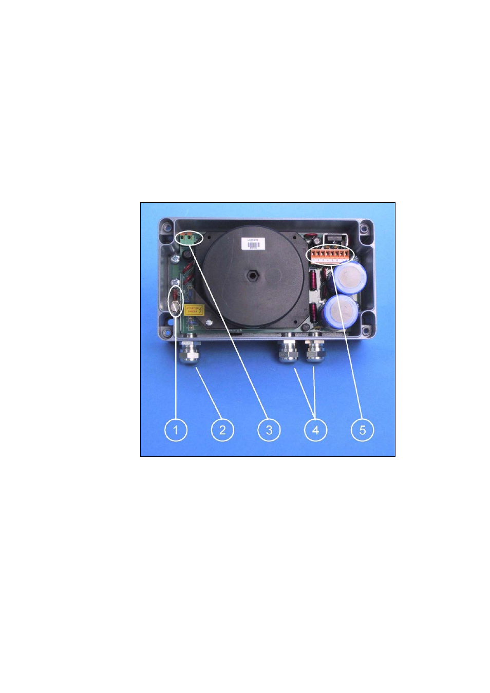
Refer to Figure 5 below for the location of the
connectors and cable glands on the WHP25 unit.
7.
Tighten the input cable glands.
0212-187
Figure 5
WHP25 Connectors and Glands
The following numbers refer to Figure 5 above.
1
=
Crimp and screw for AC (mains) grounding
2
=
Gland for AC (mains) input cable
3
=
X1: Spring loaded terminals
4
=
Glands for power output cables
5
=
X4: Removable screw terminal block