Alignment, Verification, Connector – Vaisala WAA151 User Manual
Page 14: Alignment verification, Figure 5, Waa151 connector
User's Guide ________________________________________________________
12 _____________________________________________________ M210293en-A
Alignment
The anemometer does not need any alignment after
mounting.
Verification
If your sensor is connected to the data collection system and
powered up, check that the speed readings are changing
when you rotate the cup wheel manually.
Connector
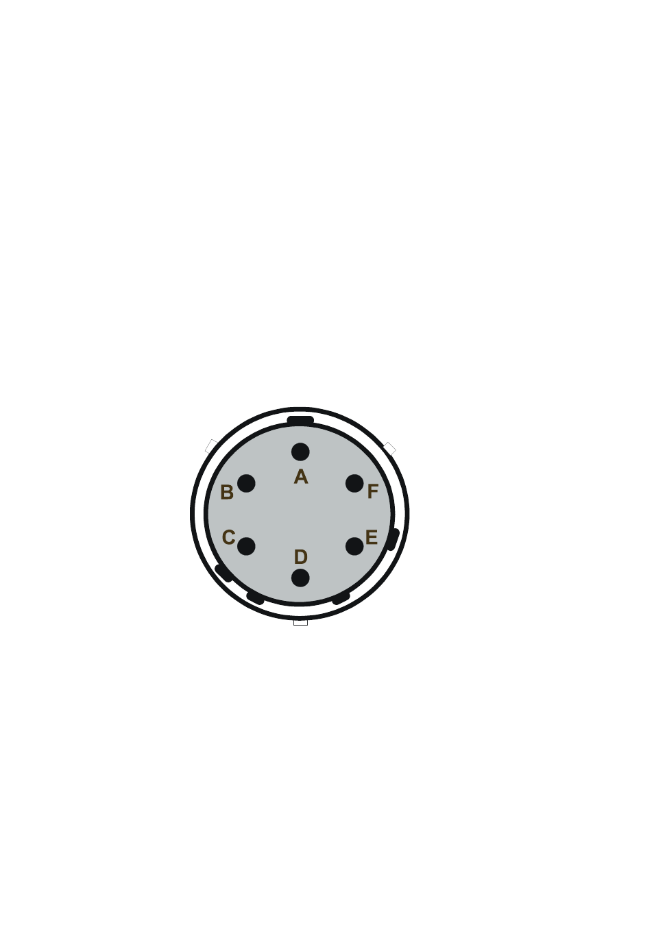
The connector for the WAA151 is shown in Figure 5 below.
0002-027
Figure 5
WAA151 Connector
The following letters refer to Figure 5 above.
A =
F+, power input from 9.5 to 15.5 VDC
B =
GND, common ground
C =
Fout, signal output
D =
HTNG, 20 VDC or VAC
E
=
HTNG, 20 VDC or VAC
F
=
Not connected