Gas supply systems, Gas pressure requirements, Supply gas regulator – State SHE75 100NE User Manual
Page 20: Dishwashing machines
20
GAS SUPPLY SYSTEMS
Low pressure building gas supply systems are defined as those
systems that cannot under any circumstances exceed 14” W.C. (1/2
PSI Gauge). These systems do not require pressure regulation.
Measurements should be taken to insure that gas pressures are
stable and fall within the requirements stated on the water heater
rating plate. Readings should be taken with all gas burning equipment
off (static pressure) and with all gas burning equipment running at
maximum rate (dynamic pressure). The gas supply pressure must
be stable within 1.5” W.C. from static to dynamic pressure to provide
good performance. Pressure drops that exceed 1.5” W.C. may cause
rough starting, noisy combustion or nuisance outages. Increases or
spikes in static pressure during off cycles may cause failure to ignite
or in severe cases damage to water heater gas control valves. If
your low pressure system does NOT meet these requirements, the
installer is responsible for the corrections.
High Pressure building supply systems use pressures that exceed
14” W.C. (1/2 PSI Gauge). These systems must use field supplied
regulators to lower the gas pressure to less than 14” W.C. (1/2 PSI
Gauge). Appliances require gas regulators that are properly sized
for the water heater input and deliver the rating plate specified
pressures. Gas supply systems where pressure exceeds 5 PSI often
require multiple regulators to achieve desired pressures. Systems in
excess of 5 PSI building pressure should be designed by gas delivery
professionals for best performance. Water heaters connected to gas
supply systems that exceed 14” W.C. (1/2 PSI Gauge) at any time
must be equipped with a gas supply regulator.
GAS PRESSURE REQUIREMENTS
All models require a minimum gas supply pressure of 3.5” W.C.(0.87
kPa) for natural gas and 8.0” W.C. (1.99 kPa) for propane. The
minimum supply pressure is measured while gas is not flowing
(static pressure) AND while gas is flowing (dynamic pressure). The
supply pressure (static and dynamic) should never fall below 3.5”
W.C.(0.87 kPa) for natural gas or 8.0” W.C. (1.99 kPa) for propane.
The supply pressure should be measured with all gas fired water
heaters connected to the common main firing at full capacity. If the
supply pressure drops more than 1.5” W.C. (0.37 kPa) as gas begins
to flow to the water heater then the supply gas system including the
gas line and/or the gas regulator may be restricted or undersized.
See Supply Gas Regulator section and Gas Piping section of this
manual. The gas control valve on all models has a maximum gas
supply pressure limit of 14” W.C.(3.48 kPa) The maximum supply
pressure is measured while gas is not flowing (static pressure) AND
while gas is flowing (dynamic pressure).
SUPPLY GAS REGULATOR
The maximum allowable gas supply pressure for this water heater
is 14 inches W.C. (3.5 kPa). Install a positive lock-up gas pressure
regulator in the gas supply line if inlet gas pressure can exceed 14
inches W.C. (3.5 kPa) at any time. Regulators must be sized/used
according to manufacturer’s specifications.
If a positive lock-up regulator is required follow these instructions:
1. Positive lock-up gas pressure regulators must be rated at or above
the input Btu/hr rating of the water heater they supply.
2. Positive lock-up gas pressure regulator(s) should be installed no
closer than 3 feet (1 meter) and no farther than 8 feet (2.4 meters)
from the water heater’s inlet gas connection.
3. After installing the positive lock-up gas pressure regulator(s) an
initial nominal supply pressure setting of 7.0” W.C.(1.74 kPa) for
Natural Gas and 11.0” W.C. (2.74 kPa) for Propane (LP) while
the water heater is operating is recommended and will generally
provide good water heater operation. Some additional adjustment
may be required later to maintain a steady gas supply pressure.
4. When installing multiple water heaters in the same gas supply
system it is recommended that individual positive lock-up gas
pressure regulators be installed at each unit.
All gas piping must comply with local codes and ordinances or with
the current editions National Fuel Gas Code (ANSI Z223.1/ NFPA-
54) or the Natural Gas and Propane Installation Code (CAN/CSA
B149.1) whichever applies. Copper or brass tubing and fittings
(except tin lined copper tubing) shall not be used.
If the gas control valve is subjected to pressures exceeding 1/2 psi
(3.5 kPa), the damage to the gas control valve could result in a fire
or explosion from leaking gas.
If the main gas line Shut-off serving all gas water heaters is used,
also turn off the gas at each water heater. Leave all gas appliances
shut off until the water heater installation is complete.
A gas line of sufficient size must be run to the water heater. Consult
the current edition of National Fuel Gas Code (ANSI Z223.1/NFPA
54) or the Natural Gas and Propane Installation Code (CAN/CSA
B149.1) and your gas supplier concerning pipe size.
There must be:
• A readily accessible manual shut off valve in the gas supply line
serving the water heater, and
• A sediment trap ahead of the gas control valve to help prevent dirt
and foreign materials from entering the gas control valve.
• A ground joint union of proper size between the manual shut off
valve and control valve to permit servicing of the unit.
Be sure to check all the gas piping for leaks before lighting the water
heater. Use a soapy water solution, not a match or open flame.
Rinse off soapy solution and wipe dry.
DISHWASHING MACHINES
All dishwashing machines meeting the National Sanitation
Foundation requirements are designed to operate with water flow
pressures between 15 and 25 pounds per square inch (103 kPa
and 173 kPa). Flow pressures above 25 pounds per square inch
(173 kPa), or below 15 pounds per square inch (103 kPa), will result
in improperly sanitized dishes. Where pressures are high, a water
pressure reducing or flow regulating control valve should be used
in the 180°F (82°C) line to the dishwashing machine and should be
adjusted to deliver water pressure between these limits.
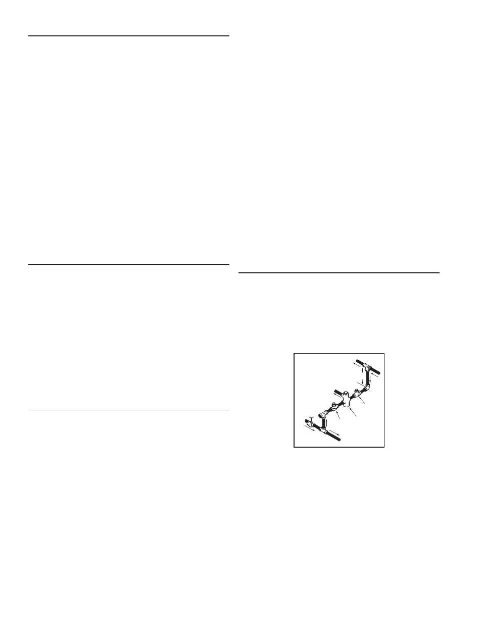
HOT WATER
OUTLET
TO TANK
INLET
CHECK
VALVE
MIXING
VALVE
COLD
WATER
INLET
TEMPERED WATER
OUTLET
12” TO 15”
(30-38 cm)
CHECK
VALVE
Figure: 9
The National Sanitation Foundation also recommends circulation of
180°F (82°C) water. The circulation should be just enough to provide
180°F (82°C) water at the point of take-off to the dishwashing
machine.
Adjust flow by throttling a full port ball valve installed in the circulating
line on the outlet side of the pump. Never throttle flow on the suction
side of a pump.
Note: To comply with NSF Standard 5 installation requirements the
bottom of the water heater must be sealed to the floor with a silicone
based sealant or elevated 6 inches above the floor.