State SDV 75 70 NE/PE User Manual
Page 9
9
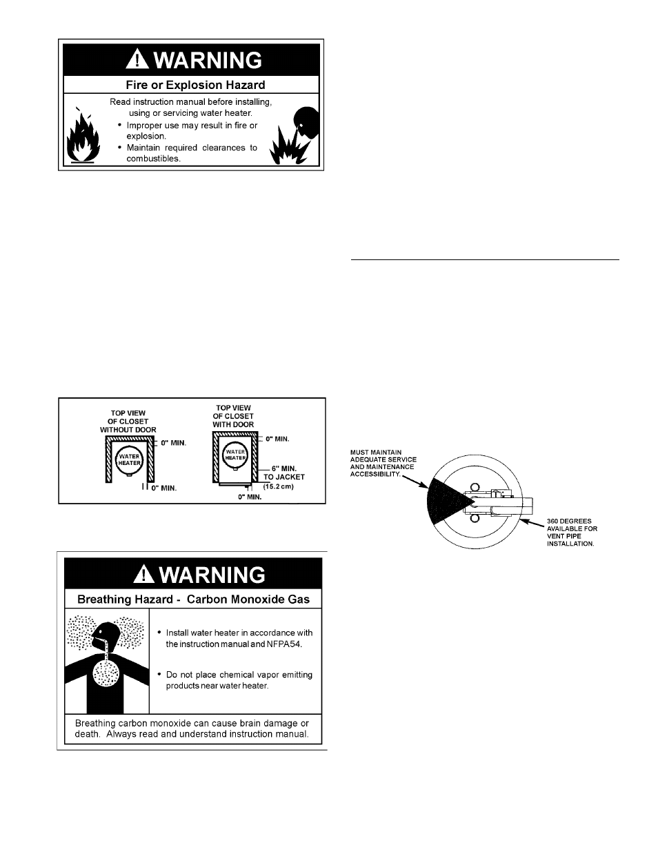
Minimum clearances between the water heater and combustible
construction are 0 inch at the sides and rear, 6” (15.2 cm) from the
front of the jacket, and 12” (30.5 cm) from the top (standard clearance).
If clearances stated on the heater differ from standard clearances,
install water heater according to clearances stated on the heater.
Adequate clearance for servicing this appliance should be considered
before installation, such as changing the anodes, etc.
A minimum clearance of 5” (12.7 cm) from the front of the jacket must
be allowed for access to replaceable parts such as the thermostats,
drain valve and relief valve. Provide 24” (61 cm) front clearance for
servicing and adequate clearance between the jacket top and ceiling
for servicing the fl ue area.
When installing the heater, consideration must be given to proper
location. Location selected should be as close to the wall as
practicable and as centralized with the water piping system as
possible.
FIGURE 4.
If this water heater will be used in beauty shops, barber shops,
cleaning establishments, or self-service laundries with dry cleaning
equipment, it is imperative that the water heater or water heaters
be installed so that combustion and ventilation air be taken from
outside these areas.
Propellants of aerosol sprays and volatile compounds, (cleaners,
chlorine based chemicals, refrigerants, etc.) in addition to being
highly fl ammable in many cases, will also react to form corrosive
hydrochloric acid when exposed to the combustion products of
the water heater. The results can be hazardous, and also cause
product failure.
COMBUSTION AIR AND EXHAUST TERMINATION
CLEARANCES
Venting Through an Outside Wall - Clearances, see Figure 6.
• 0" clearance for 3" PVC, ABS, or CPVC Schedule 40 piping from
combustible surfaces.
• The location selection must provide clearances for servicing and
proper operation of the water heater, see Figure 7.
FIGURE 5.
• The venting system must be installed in a manner which allows
inspection of the installation of the venting pipes and joints as
well as periodic inspection after installation as required by the
National Fuel Gas Code ANSI Z223.1-current edition.