Outback Power Systems FLEXpower ONE Quick Start Guide User Manual
Components, Mate3 programming, Major components
> 90% (blinks if charge parameters are met)
Color
Red
Yellow
Yellow
Yellow
Green
≥ 80%
≥ 70%
≥ 60%
≥ 60% off, < 60% solid, < 50% blinks
Battery State-of-Charge
FNDC LED Indicators
Components
900-0132-01-00 Rev A.vsd\Page-1\2013-01-17
©2012 OutBack Power Technologies. All Rights Reserved.
MATE3 Programming
Contact Technical Support:
Telephone: +1.360.618.4363
Email:
Website:
www.outbackpower.com
MATE RTS
AC
IN
INV
MAIN----------------
3:02:14P
SUM STATUS SETUP ADV
In 23.2 V 0.0 A
Out 27.6 V 0.0 A
0.000 kW 0.0 kWH
AUX: OFF Sleeping
MATE
RTS
MATE
RTS
A
C
HO
T
OU
T
A
C
NE
UT
R
A
L O
U
T
C
H
A
S
S
IS
GR
OUND
/P
E
C
H
A
S
S
IS
GR
OUND
/P
E
A
C
NE
UT
R
A
L
IN
AC
H
O
T
I
N
FW250-AC-120V-NA
FW250-DC-125
(175 or 250)
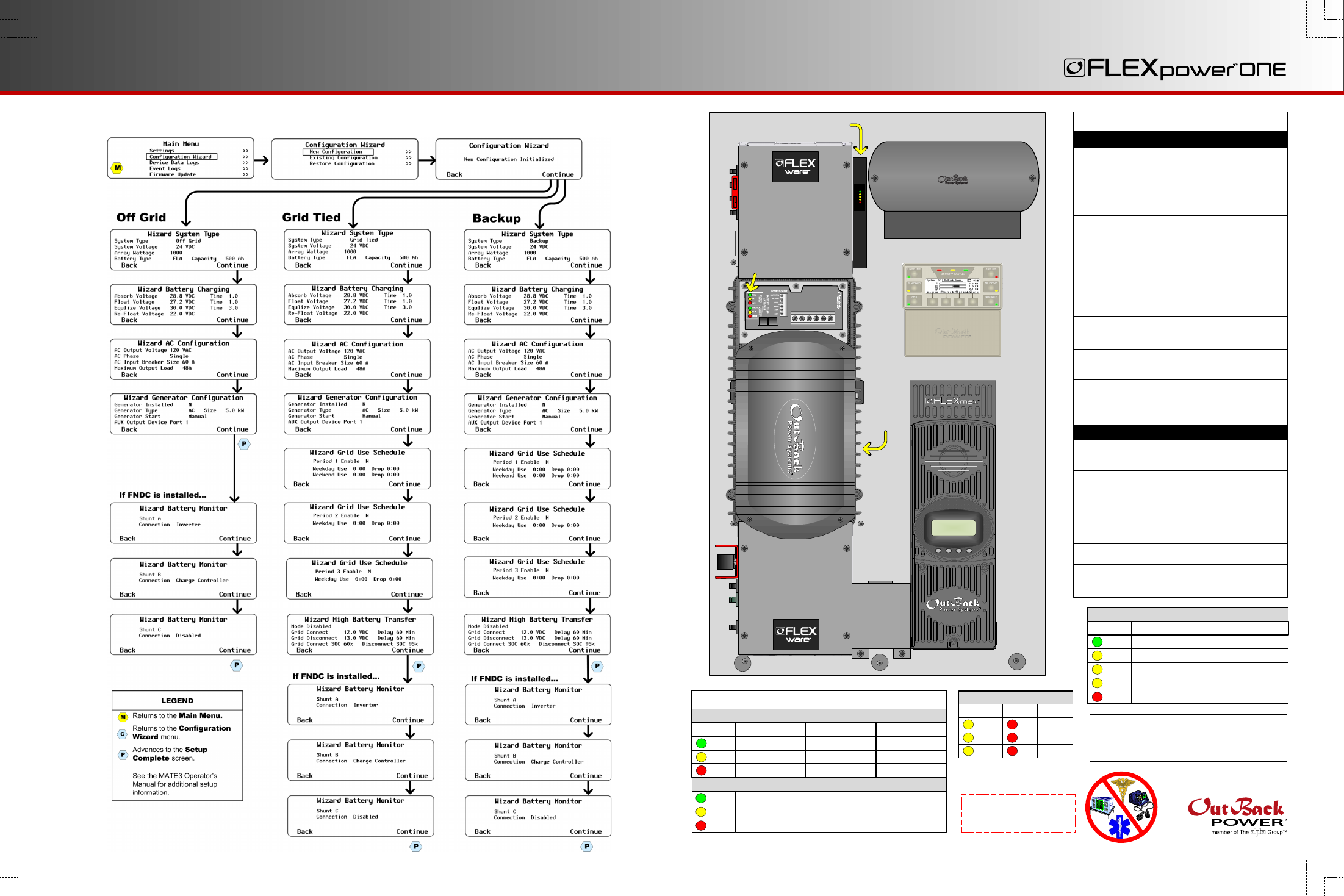
Charge Controller
(FLEXmax 80)
FLEXnet DC
Battery Monitor
Surge Protector
(Inside)
Inverter/
Charger
System Display and Controller
(MATE3)
HUB Communication Manager
(HUB4 or HUB10)
Battery Status LEDs
Inverter Status LEDs
IMPORTANT:
Programming should be done by a qualified installer who is trained on programming inverter power systems. Failure to program accurate parameters for the
system could potentially cause equipment damage. Damage caused by inaccurate programming is not covered by the limited warranty for the system.
Inverter/Charger
AC Conduit Box
FW250-AC-120V-NA
DC Conduit Box
FW250-DC-125
FW250-DC-175
FW250-DC-250
System Display and
Controller
MATE2
MATE3
Charge Controller
FLEXmax 60
FLEXmax 80
Communications
Manager
HUB4
HUB10
AC Source
Utility Grid, or
AC Generator
Main Electrical Panel
(or overcurrent device for AC source)
Electrical Distribution Subpanel
(Load Panel)
Battery Bank
Photovoltaic (PV) Array
(with PV Combiner Box [PV8 or PV12])
FX Series
VFX Series
GTFX Series
GVFX Series
GFX Series
Remote Temp Sensor RTS
FLEXnet DC Monitor FNDC
Surge Protector
FW-SP-ACA
Customer-Supplied Components
FLEXpower System Products
Major Components
IMPORTANT:
Not intended for use with
life support equipment.
Phase
Active
Error
DC
AC IN
AC OUT
Red
Yellow
Yellow
Yellow
Red
Red
Surge Protector LEDs
LED Indicators on the Inverter
Inverter Status LED Indicators
Green
Yellow
Red
Inverter on (solid) or standing by (flash)
AC source in use (solid) or standing by (flash)
Inverter error or warning (see manual)
Green
Yellow
Red
12.5 Vdc or higher
11.5 to 12.4 Vdc
11.4 Vdc or lower
Color
Battery Status LED Indicators
25.0 Vdc or higher
23.0 to 24.8 Vdc
22.8 Vdc or lower
50.0 Vdc or higher
46.0 to 49.6 Vdc
45.6 Vdc or lower
12 V Inverter
24 V Inverter
48 V Inverter