Radian series, Wire sizes/torque requirements, Mounting – Outback Power Systems GS8048 Quick Start Guide User Manual
Page 2: Warning: personal injury, Warning: fire/explosion hazard, Important, Radian mounting, Ac wire sizes and torque values
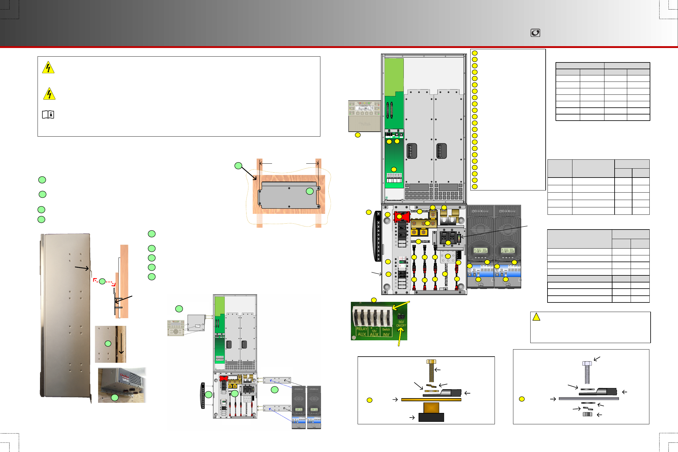
5. Secure the inverter to the surface using a minimum
of 1 wall screw (or other appropriate hardware).
6. Follow the instructions for installing the GS Load Center.
7. Follow the instructions for installing the HUB Communication Manager.
8. Follow the instructions for installing the brackets for the charge controllers.
9. Follow the instructions for installing the bracket for the MATE3.
Wire Sizes/Torque
Requirements
Control Wiring Terminal Block:
The Inverter ON/OFF terminals are used for connecting an
external ON/OFF switch. To use this feature, the jumper
must be removed. (See Radian manual for details.)
The AUX terminals can be used to start a generator
or to control external devices.
AUX terminals are also available on the charge
controller and the FLEXnet DC. (See the charge
controller or FNDC installation manuals for details.)
Mounting
WARNING: Fire/Explosion Hazard
Do not place combustible or flammable materials within 12 feet (3.7 m) of the equipment. This unit employs mechanical
relays and is not ignition-protected. Fumes or spills from flammable materials could be ignited by sparks.
WARNING: Personal Injury
Use safe lifting techniques and standard safety equipment when working with this equipment.
IMPORTANT:
Clearance and access requirements may vary by location. Maintaining a 36” (91.4 cm) clear space in front of the system
for access is recommended. Consult local electric code to confirm clearance and access requirements for the specific
location.
Radian Dimensions (includes MATE3 and 2 FLEXmax 80 Charge Controllers):
29.1" (85 cm) tall X 35.4" (50 cm) wide
900-0153-01-00 Rev A.vsd\Page-2\2013-01-17
©2012 OutBack Power Technologies. All Rights Reserved.
Torque Requirements
Circuit Breaker Stud
Torque
In-lb
Nm
M8
20
2.3
¼ - 20
35
4.0
5/16 - 18
50
5.6
3/8 - 16
225
25.4
AC Wire Sizes and Torque Values
It is recommended that conductors be #6 AWG
THHN copper, or larger, rated to 75°C
(minimum) unless local code requires otherwise.
AWG
In-lb
#14 - 10
20
#8
25
#6 - 4
35
#3
35
#2
40
#1
50
1/0
50
mm
2
2.5 – 6
10
16 – 25
35
35
50
70
Nm
2.3
2.8
4.0
4.0
4.5
5.6
5.6
Wire Size
Torque
Radian Mounting:
1. Ensure the mounting surface is strong enough to handle 3 times the total weight of
all the components. Add a piece of plywood if necessary to strengthen the surface.
2. Attach the wall bracket to the surface centering the mounting holes on the sides
with the wall studs. Use all 6 mounting screws to secure the bracket.
3. Lift the inverter so that the inverter bracket is above the wall bracket.
4. Lower the Inverter into place so that the inverter bracket slips into the wall bracket.
1
3
4
6
RADIAN Series
N
E
U
L1 L2
GRID
L1 L2
GEN
N
E
U
N
E
U
L1 L2
OUT
RELAY
AUX
+ -
12V
AUX
Switch
INV
Remote
Battery
Temp
Charge
Controller #1
Charge
Controller #2
Minimum DC Cable based on the
DC Circuit Breaker
Torque
In-lb
Nm
50
5.6
225
25.4
225
25.4
DC
Circuit
Breaker
Cable Size
125
1/0 (70 mm
2
)
175
2/0 (70 mm
2
)
250
4/0 (120 mm
2
)
35
4.0
80
#4 AWG (25 mm
2
)
35
4.0
60
#6 AWG (16 mm
2
)
MATE3
HUB10
GS8048
GSLC
1
2
FNDC
2
3
4
5
7
8
8
9
9
9
9
9
10
10
10
6
ON/OFF
INV
10
Jumper
AC Circuit Breakers
1
GFDI
2
3
4
DC Terminals - Inverter
AC Terminals - Inverter
5
DC Circuit Breakers
6
PV Circuit Breakers
PV Input/Output Terminals
7
8
Mechanical Interlock (Bypass)
9
10
Communication Ports
Auxiliary Terminals
Plywood
(Optional)
Wall Board
Wall
Bracket
Wall Stud
Side View
Inverter
Bracket
16" (40.6 cm)
Plywood (Optional)
Wall Board
Wall Stud
Wall Bracket
Wall Stud
1
2
2
3
4
5
5
6
7
8
9
9
8
11
12
13
14
15
AC OUT Bus Bar L1
16
17
18
19
AC OUT Bus Bar L2
GRID IN Bus Bar L1
GRID IN Bus Bar L2
GEN IN Bus Bar L1
GEN IN Bus Bar L2
AC Neutral
Ground
20
DC Positive (+) Plate
DC Negative (–) Bus Bar
11
12
13
14
15
16
17
18
19
20
21
22
PV Positive (+) Bus Bars
DC Negative (–) Plate (GS-SBUS)
21
21
Radian Series
Inverter/Charger
MATE3
Mounting
Bracket
MATE3
HUB
Communication
Manager
GS Load Center
Charge Controller
Mounting Bracket
Charge Controller
Mounting Bracket
FLEXmax 80
Charge Controllers
7
Bolt 3/8"
DC Positive (+)
Plate
Battery
Positive (+)
Lug
Flat Washer
Positive Battery Cable
Connections
Nut
Lock Washer
Flat Washer
Shunt
Bolt 3/8"
Lock Washer
Flat Washer
Battery
Negative (–)
Lug
Negative Battery Cable
Connections
DC
Negative (-)
Plate
22
22
19
DC Plates
3/8 - 16
225
25.4
Upper holes (+)
60
6.8
3/8 - 16
225
25.4
Lower holes (+)
225
25.4
3/8 - 16
225
25.4
Shunt Bolts (–) and GS-SBUS
60
6.8
Lower holes (+)
50
5.6
CAUTION: Equipment Damage
When connecting cables from the inverter to the battery
terminals, ensure the proper polarity is observed.
Connecting the cables incorrectly can damage or
destroy the equipment and void the product warranty.
!