Dimensions, Component drawing – Griffco Valve CCG Glass User Manual
Page 2
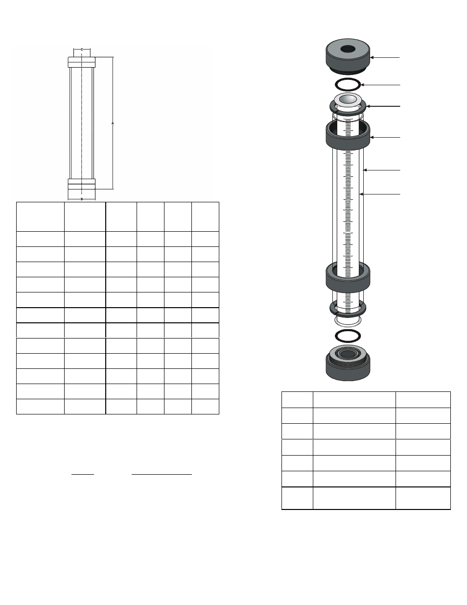
Dimensions:
Capacity
(mL)
Size
(USgph)
Scale
(mL)
A
(in)
B
(in)
C
(in)
30
.95
1
14
1.4
1/4
100
3.2
2
15
2.5
1/2
200
6.4
2
21
2.5
1/2
500
16
5
15
3.5
3/4
1,000
32
5
27
3.5
3/4
2,000
63
10
27*
5.0
1
3,000
95
10
21
7.5
1 1/2
4,000
127
10
39*
5.0
1
5,000
160
10
29
7.5
1 1/2
7,000
225
10
39
7.5
1 1/2
10,000
320
20
27
9.15
2
20,000
640
20
39
9.15
2
* 2,000mL w/ PTFE End Cap ONLY, Dim A = 26 in
* 4,000mL w/ PTFE End Cap ONLY, Dim A = 38 in
Codes for Ordering Glass Calibration Cylinders:
CCG □□□□□ □
1
2
1 = Size
2 = End Cap Material
0030 - 30 mL
0100 - 100 mL
P - PVC
0200 - 200 mL
CP - CPVC
0500 - 500 mL
PP - Polypro
1000 - 1000 mL
T - PTFE
2000 - 2000 mL
K - PVDF
4000 - 4000 mL
M - 316 SS
10000 - 10000mL
A - Alloy 20
20000 - 20000 mL
Component Drawing:
6
4
5
3
2
1
Ref #
Part # - Size - Mtrl
Description
1
PC-001-_____ - ___
End Cap
2
PC-002-_____ - V
O-Ring
2
3
PC-003-_____ - PVC
Split Ring
4
PC-004-_____ - PVC
Nut
5
PC-005-_____ - CAB
Shield
1
6
PC-006-_____ - GL
Glass
Tube
1
Shield not available on 10 & 20,000 mL sizes.
2
Viton O-Ring is standard, other by request.
When ordering parts please specify size and
material code.
Website: www.griffcovalve.com
Email: [email protected]