Installation, 1 basic connection – AVE MV DR4000 User Manual
Page 12
10
3. INSTALLATION
Please follow the instructions and the diagram below to set up the system.
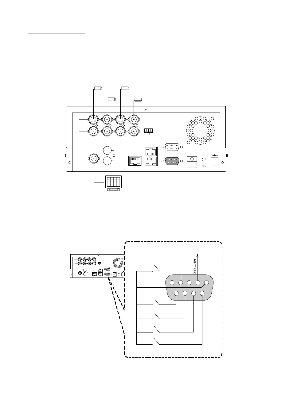
3.1 Basic Connection
CONNECTING WITH 1 to 4 CAMERAS
Camera
Monitor
Camera
Camera
Camera
RS-232
ALARM
DC12V
RS-485
hi-z
75
AUDIO
IN
IN
OUT
OUT
MONITOR
ETHERNET
I/O
ATTACHING AN EXTERNAL DEVICE TO DVR
Connect an alarm out, alarm input, and a peripheral device as shown in the diagram below.
Alarm In -> Alarm1 In, Alarm2 In, Alarm3 In, Alarm4 In
RS-232
ALARM
DC12V
RS-485
hi-z
75
AUDIO
IN
IN
OUT
OUT
MONITOR
ETHERNET
I/O
1
2
3
4
5
6
7
8
9
Alarm Reset
(Normally Open)
(Normally Open)
Alarm1 in
(Normally Open)
Alarm2 in
(Normally Open)
Alarm3 in
(Normally Open)
Alarm4 in
Ground
Trigger Out