Connections and operation, Continued – Anthem P5 User Manual
Page 7
2. CONNECTIONS AND OPERATION
continued …
WARNING
WARNING
2.4
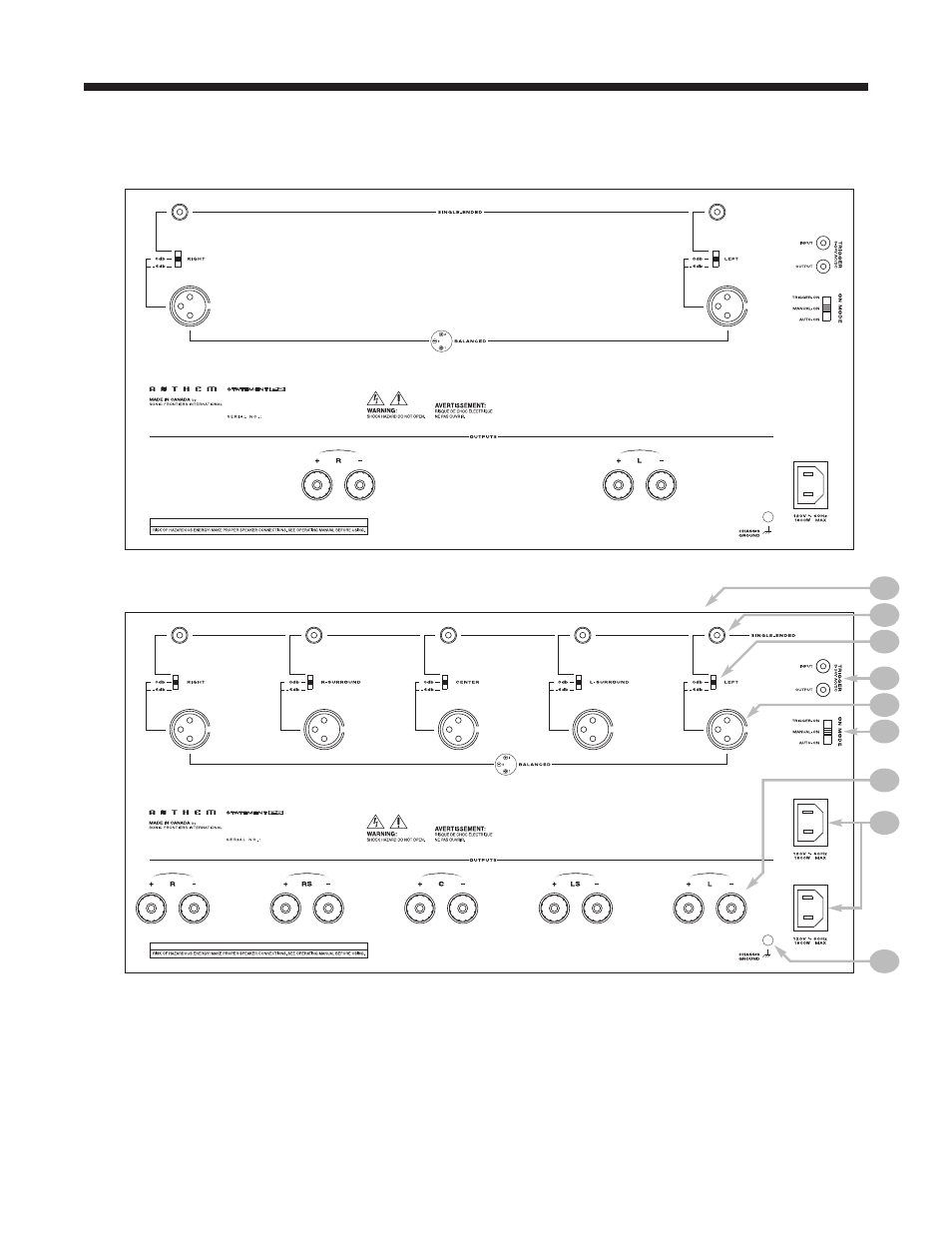
REAR PANEL LAYOUT
1 – Circuit breakers (not shown – located on top)
2 – Single Ended RCA Input
3 – Input/Gain Selector
4 – Trigger Input and Output
5 – Balanced XLR Input
6 – On-Mode (Trigger / Manual / Auto)
7 – Speaker Binding Posts
8 – Power Cord Socket (2 for Statement P5)
9 – Chassis Ground
1
2
3
4
5
7
8
9
STATEMENT P2
STATEMENT P5
6
This manual is related to the following products: