Rear panel – Manley LANGEVIN ELECTRO-OPTICAL LIMITER User Manual
Page 8
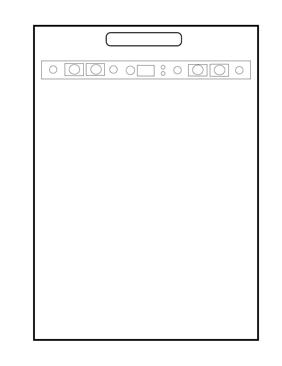
REAR PANEL
8
E
F
A
B
D
C
H
G
J
K
A
1/4" INPUT (BALANCED) (RIGHT)
TIP: HOT
SLEEVE: GROUND
Any of the "balanced inputs can be used with unbalanced sources
B
XLR INPUT (BALANCED) (RIGHT)
PIN 1: GROUND
PIN 2: HOT (+)
PIN 3: GROUND
C
1/4" OUTPUT (UNBALANCED) (RIGHT)
TIP: HOT
SLEEVE: GROUND
Use only 1/4" MONO (tip - sleeve) plugs with these jacks otherwise levels will be low.
D
XLR OUTPUT (BALANCED) (RIGHT)
PIN 1: GROUND
PIN 2: HOT (+)
PIN 3: GROUND
E
IEC MAINS CONNECTOR Standard IEC mains connector for 50 /60 Hz AC.
F
MAINS FUSE Replace with only a 1 Amp slo-Blo fuse.
G
XLR INPUT (BALANCED ) (LEFT)
PIN 1: GROUND
PIN 2: HOT (+)
PIN 3: GROUND
H
1/4"INPUT (BALANCED ) (LEFT)
TIP: HOT
SLEEVE: GROUND
I
XLR OUTPUT (BALANCED) (RIGHT) PIN 1: GROUND
PIN 2: HOT (+)
PIN 3: GROUND
J
1/4" INPUT (UNBALANCED) (RIGHT)
TIP: HOT
SLEEVE: GROUND
Use only 1/4" MONO (tip - sleeve) plugs with these jacks otherwise levels will be low
K
GROUND TERMINALS
BLACK = CIRCUIT GROUND
or "Audio Ground"
GREEN = CHASSIS GROUND
or "Electrical Ground" ie mains pin 3
Generally these two ground terminals are connected together with the included "ground strap"
(a small flat piece of metal) but they can be individually used for different grounding systems.
Another use for these is in troubleshhoting HUM problems. Experiment with attaching a wire from
the console to only the BLACK terminal or connecting the GREEN to a rack, (etc).
I