FanAm COMPAX Series User Manual
Page 3
Detailed Installation Instructions
1. Provide a solid frame against which the unit will
be mounted (see dimensional data for proper frame
sizing). Make sure that the housing will be flush with
the finished ceiling, once the unit has been fixed into
the frame.
2. Bend mounting bracket and fasten it in desired
location in the ceiling.
3. Mount brackets with self-drilling tap screws in
desired position on the unit housing. Fan mounting
brackets are adjustable vertically on the fan housing.
4. Hang unit. Tighten mounting screws as firmly as pos-
sible to assure secure support and lowest possible
sound levels. Note: A secure solid frame will also help
sound levels to remain at a minimal.
5. Wire unit.
Turn power off at circuit breaker or fuse panel
a) Remove desired knockout and open fan
terminal box from inside the fan.
Connect incoming electric supply per wiring
diagram.
b) Use appropriate electrical connector and strain
relief to secure the incoming electric cable.
6. Connect ductwork to the collars 4 and 5 inch.
Tape joints with duct tape.
7.Reattach lid with screws.
Wiring Diagrams
Using Current Sensor
DRYER JUNCTION BOX
POWER TO DRYER
NEUTRAL/WHITE
120 VAC
COMPAX FAN
CURRENT
SENSOR
WITH TIMER
120 VAC
Supply Voltage
Neutral (White lead)
Hot (Black lead)
Hot (Gray lead)
Neutral (White lead)
Supply
Voltage
For Fan
Neutral (white lead) from dryer
N1
L1
L2
N2
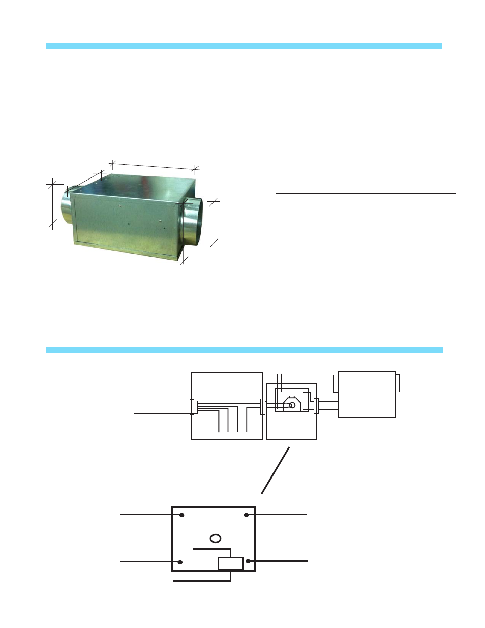
All dimensions in inches
12
11
4 7/8
6.5
Outlet
Inlet
5