Ashland L-10 User Manual
Page 7
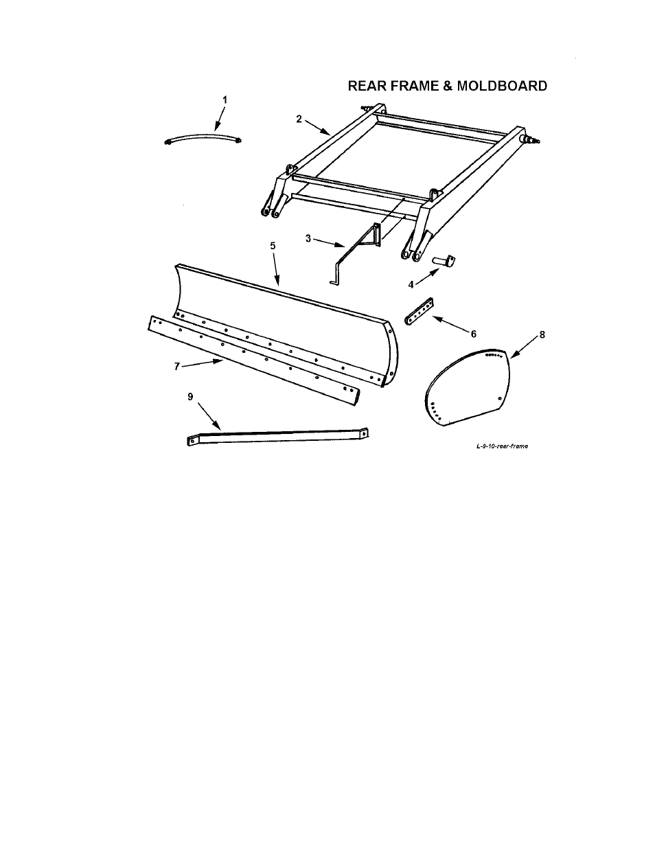
KEY NO. PART NO.
DESCRIPTION
1
A45H06
Hydraulic hose, 1/2" x 24" (4 req’d)
2
A906
Rear frame section
3
A908
Depth gague pointer
4
A911
Pin, 1-1/2" x 6" with grease hole
(uses 1/2 x 1" NC capscrew w/ lockwasher)
5
A904
Moldboard assembly, 9 ft.
A913
Moldboard assembly, 10 ft.
6
A907
Tilt Bracket
7
A905
Cutting edge, 9 ft.
A10S02
Cutting edge, 10 ft.
Plow Bolt, 1/2" NC x 1-3/4", (12 req’d 10ft or 11 req’d 9 ft.)
8
A910
Moldboard end plate (right and left same)
(uses 3/4" x 1-1/2" bolt at bottom rear
and 1/2" by 1-1/2" bolt at top)
9
A909
End plate brace for 9 ft. moldboard
(uses 5/8" x 2" bolt at frame and 5/8" x 1-1/2"
at end plate)
A914
End plate brace for 10 ft. moldboard
7
This manual is related to the following products:
See also other documents in the category Ashland Gardening equipment:
- I-950 ver 1211 (38 pages)
- I-110TS2 ver 1111 (36 pages)
- I-110XL2 ver 1111 (34 pages)
- I-130TS2 ver 1111 (36 pages)
- I-130XL2 ver 611 (40 pages)
- I-155-TS2 ver 1111 (38 pages)
- I-155XL2 ver 0811 (34 pages)
- I-175XL2 ver 811 (34 pages)
- I-180TS2 ver 1011 (46 pages)
- I-200TS4 ver 0612 (32 pages)
- 10S (6 pages)
- 25D (12 pages)
- 35D (12 pages)
- I-180TS2 (33 pages)
- I-180TS2 (25 pages)
- 45 (15 pages)
- 450 (21 pages)
- 61D (13 pages)
- 70D (15 pages)
- 80D (16 pages)
- I-80 (20 pages)
- I-900 Ver 1-2007 (22 pages)
- I-900 Ver10-2008 (24 pages)
- I-110 (23 pages)
- I-110-SP (25 pages)
- I-110XL2 (33 pages)
- I-110TS (32 pages)
- I-110TS2 (23 pages)
- I-130 (28 pages)
- I-130-SP (21 pages)
- I-130TS2 (30 pages)
- I-130TS2 (22 pages)
- I-130XL2 Ver 3-2007 (38 pages)
- I-130XL2 Ver 3-2009 (25 pages)
- I-140 (28 pages)
- I-150SP (24 pages)
- I-155-TS (51 pages)
- I-155XL (21 pages)
- I-155XL2 Ver 8-2006 (37 pages)
- I-155XL2 Ver 7-2008 (24 pages)
- I-160 (23 pages)
- I-160 XL (21 pages)
- CS18-HD (17 pages)
- I-175XL (23 pages)
- I-175XL2 (25 pages)