American Fibertek MR-10 User Manual
Page 3
3
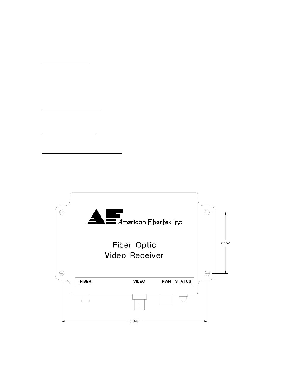
Mount the unit to a secure surface using #8 (3mm) hardware in four places. See the
drawing at the bottom of this page for mounting dimensions. Be sure to allow sufficient
room for the required minimum bend radius of the fiber cable used.
POWER SOURCE
THIS PRODUCT SHALL BE POWERED BY A LISTED CLASS 2 POWER SUPPLY
ONLY.
This unit requires a 24 VAC power source with an isolated output for proper operation.
In the USA and in Canada an American Fibertek PS-24 is supplied with this unit.
ANSI/NFPA 70 Class 2 wiring is recommended.
POWER CONNECTION
Power is supplied to the unit via a two pin terminal connector. See the labeling on the
unit and the drawing on the next page for proper location of the 24 volt ac input.
FIBER CONNECTION
The fiber optic connection is made via a ST connector located on the side of the unit.
VIDEO OUTPUT CONNECTION
The video output connection is made via a BNC connector on the side of the unit. The
75
Ω
video output can be looped through typical baseband video inputs of switchers,
recorders and other equipment as required. For proper operation, the output must be
terminated with 75
Ω
. For optimum performance the video cables should be the shortest
length of coax practical.