American Fibertek MR-911C-SL User Manual
Page 4
4
VIDEO INPUT CONNECTION
The video input connection is made via a BNC connector. The video input should be connected to an
appropriate 75
baseband video source such as a camera or a video recorder output. For optimum
performance the video cables should be the shortest length of coax practical.
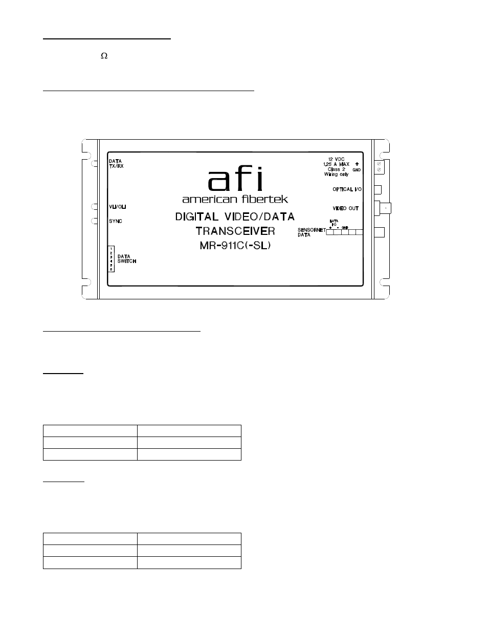
SENSORNET INPUT / OUTPUT CONNECTIONS
Data input and output connections are made via a terminal block on the right side of the unit. Follow the
label on the MR-911C-SL for proper orientation of Sensornet data input/output wires.
MR-911C-SL STATUS INDICATORS
The MR-911C-SL transmitter provides the following LED status indicators to aid in installation and
troubleshooting:
DATA TX
A green LED indicator is provided to monitor the data coming in from the electrical interface, through
the MR-911C-SL, and out onto the fiber. The intensity of this indicator will vary with input data patterns.
However, in typical applications it will cycle on and off as data is transmitted. Data transmitted status
associated with this LED is summarized below.
DATA TX LED
Data Status
Green
Data Flow Present
Off
Data Flow Not Detected
DATA RX
A green LED indicator is provided to monitor the data coming in from the fiber, through the MR-911C-
SL, and out onto the electrical interface. The intensity of this indicator will vary with input data patterns.
However, in typical applications it will cycle on and off as data is received. Data received status
associated with this LED is summarized below.
DATA RX LED
Data Status
Green
Data Flow Present
Off
Data Flow Not Detected