American Fibertek MT-913C-SL User Manual
Page 5
5
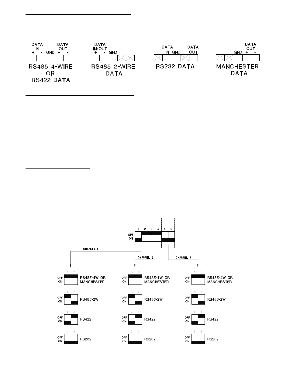
DATA INPUT / OUTPUT CONNECTIONS
Data input and output connections are made via terminal blocks on the right side of the unit. See the
drawings below for proper orientation of input and output connections. Please note that the far right pin
on each connection drawing corresponds with the terminal block pin located closest to the base of the
unit.
TYPICAL SYSTEM DATA CONNECTIONS
The RS422 or RS485 four wire interconnection between the MT-913C-SL and the copper device to
which it is attached is based on industry standard EIA terminology for the transmission of electronic
data signals. Using this terminology, the driver of an electronic signal is labeled TX or Data Out.
Correspondingly, the receiver of an electronic signal is labeled RX or Data In. Following this standard,
the Data Out of the copper device is connected to the Data In of the MT-913C-SL. The plus terminal of
the copper device is connected to the plus terminal of the MT-913C-SL and the minus is connected to
the minus. The reverse flow of data from the MT-913C-SL to the copper device follows the same
pattern. Not all manufactures follow standard EIA terminology. Consult the installation instructions for
your copper device if you are unsure which two wires are the drive (data out) wires and which two wires
are the receive (data in) wires.
DATA CONFIGURATION
NOTE: This unit is shipped in the following default configuration.
Channel 1: RS422 data
Channel 2: RS485 (4 wire) or Manchester data
Channel 3: RS232 data
For other configurations, please refer to the drawing below for changes to the default switch settings.
These configuration switches are located on the left side of the unit and can be modified without
opening the unit.
Refer to FUNCTIONAL DESCRIPTION section for a list of allowable channel
configurations.