American Fibertek MT-91P558 User Manual
Page 4
4
POWER CONNECTION
Power is supplied to the unit via a two pin terminal connector on the right side of the unit. Follow the
label on unit for proper orientation of +12 volt dc and ground.
FIBER CONNECTION
The fiber optic connection is made via a ST connector located on the right side of the unit.
VIDEO INPUT CONNECTION
The video input connection is made via a BNC connector on the right side of the unit. The video input
should be connected to an appropriate 75
Ω baseband video source such as a camera or a video
recorder output. For optimum performance the video cables should be the shortest length of coax
practical.
AUDIO INPUT / OUTPUT CONNECTIONS
Audio input and output connections are made via a terminal block on the right side of the unit. Follow
the label on unit for proper orientation of input and output connections. Please note that the far right pin
on the label (DATA OUT-) corresponds with the terminal block pin located closest to the base of the
unit.
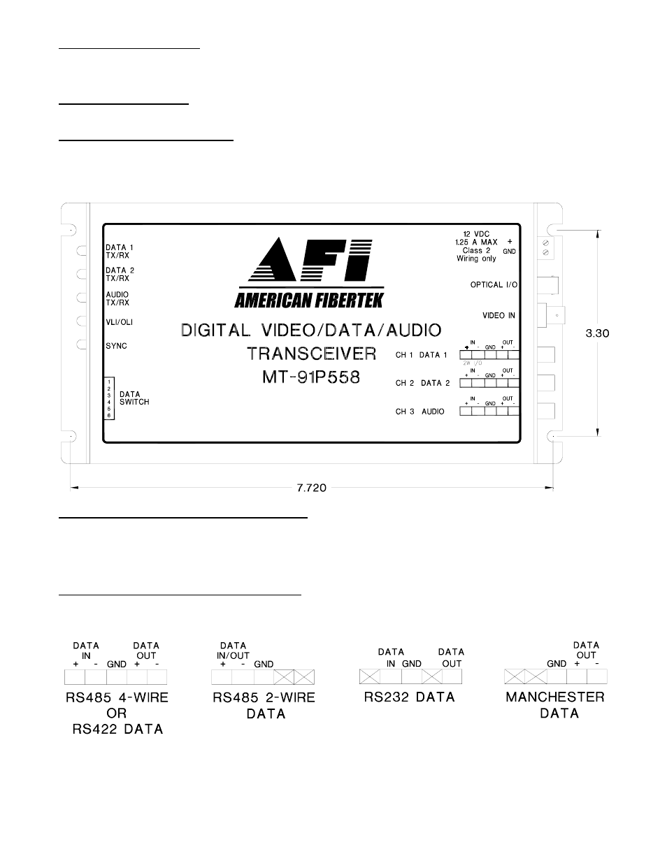
DATA INPUT / OUTPUT CONNECTIONS
Data input and output connections are made via terminal blocks on the right side of the unit. See the
drawings below for proper orientation of input and output connections. Please note that the far right pin
on each connection drawing corresponds with the terminal pin located closest to the base of the unit.