American Fibertek RR-91P089 User Manual
Page 3
3
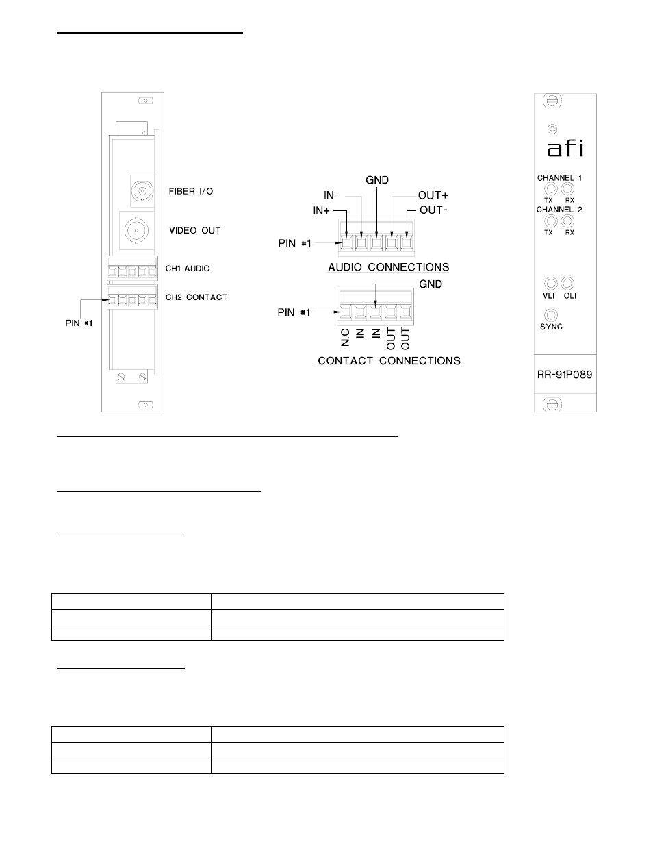
VIDEO OUTPUT CONNECTION
The video output connection is made via a BNC connector on the right side of the unit. The 75
Ω video
output can be looped through typical baseband video inputs of switchers, recorders and other
equipment as required. For proper operation, the output must be terminated with 75
Ω. For optimum
performance the video cables should be the shortest length of coax practical.
AUDIO AND CONTACT INPUT / OUTPUT CONNECTIONS
Audio and contact closure input and output connections are made via terminal blocks on the back of
the unit. See the drawing above for proper orientation of these connections.
RR-91P089 STATUS INDICATORS
The RR-91P089 transmitter provides the following LED status indicators to aid in installation and
troubleshooting:
AUDIO/CONTACT TX
A green LED indicator is provided to monitor the audio / contact closure coming in from the electrical
interface, through the RR-91P089, and out onto the fiber. The intensity of this indicator will vary with
input audio levels; however in typical applications it will cycle on and off as audio is transmitted. Audio /
contact closure transmission status associated with this LED is summarized below.
AUDIO/CONTACT TX LED
Audio/Contact Closure Status
Green
Audio Present at Proper Signal Level/Contact Closed
Off
Audio Signal Not Detected/Contact Open
AUDIO/CONTACT RX
A green LED indicator is provided to monitor the audio / contact closure coming in from the fiber,
through the RR-91P089, and out onto the electrical interface. The intensity of this indicator will vary
with input audio levels; however in typical applications it will cycle on and off as audio is received.
Audio / contact closure received status associated with this LED is summarized below.
AUDIO/CONTACT RX LED
Audio/Contact Closure Status
Green
Audio Present at Proper Signal Level/Contact Closed
Off
Audio Signal Not Detected/Contact Open