American Fibertek RR-940C User Manual
Page 3
3
POWER SOURCE
Power to the unit is supplied by the subrack. Please refer to the SR-20 and PSR instructions for
further details.
POWER CONNECTION
Power is supplied to the unit via a four finger backplane connector. The RT-940C can be
inserted into the subrack or removed from the subrack with power applied to the backplane.
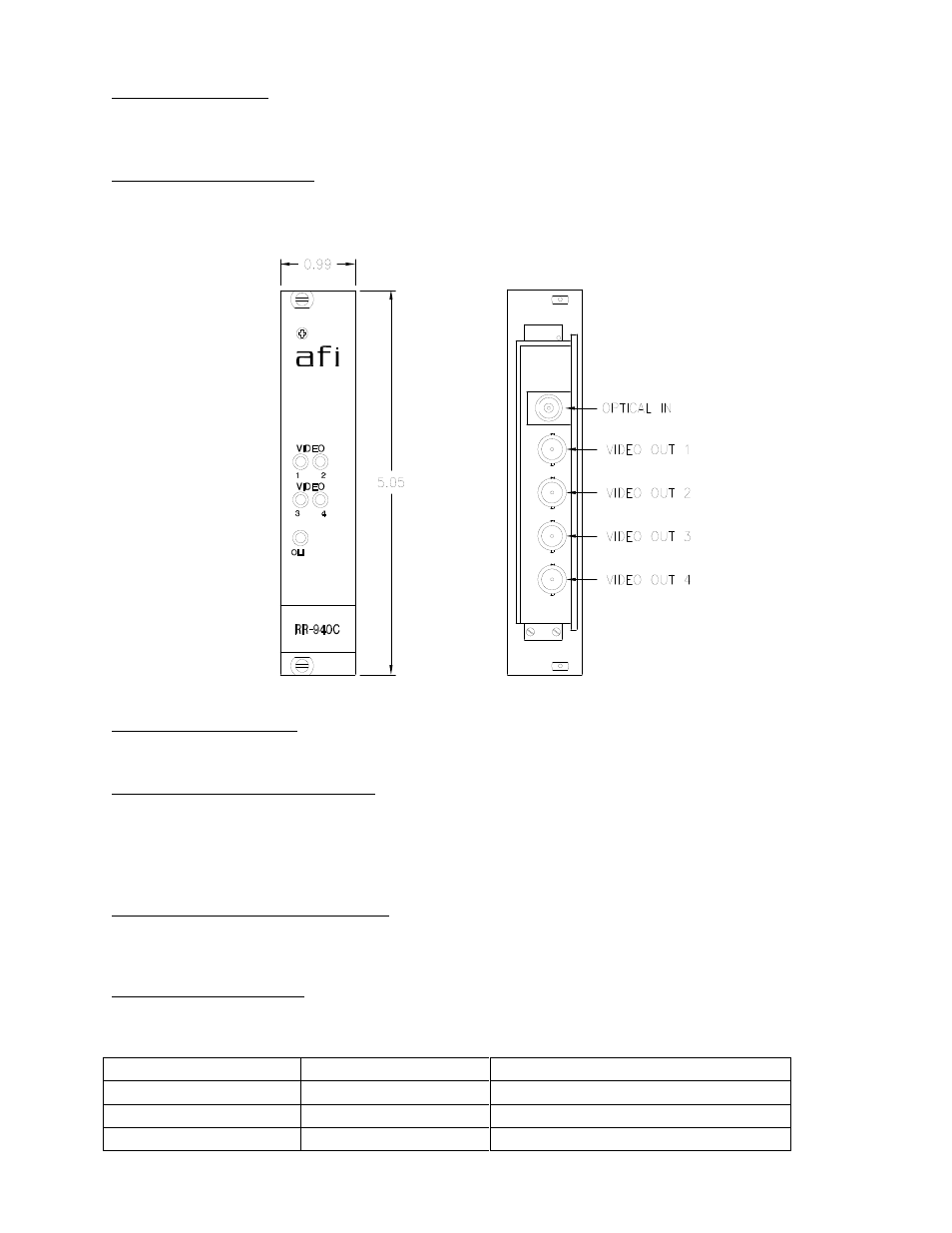
FIBER CONNECTION
The fiber optic connection is made via a FC/PC connector located on the right side of the unit.
VIDEO INPUT CONNECTIONS
The video input connections are made via BNC connectors on the right side of the unit. The
video input should be connected to an appropriate 75
baseband video source such as a
camera or a video recorder output. For optimum performance the video cables should be the
shortest length of coax practical.
RR-940C STATUS INDICATORS
The RR-940C transmitter provides the following LED status indicators described below to aid in
installation and troubleshooting:
VLI 1 THROUGH VLI 4
A bi-color LED indicator is provided for each of the four video inputs to the RR-940C. DC power
and video status associated with each of these LED’s are summarized below.
Video Presence LED
DC Power Status
Video Status
Green
On
Proper Input Video Present
Red
On
Input Video Not Detected
Off
Off
Check Power Supply