American Fibertek RR-93200D-SL User Manual
Page 5
5
POWER SOURCE
Power to the 980D series rack cards and the RD-20D rack card is supplied by the subrack.
Please refer to the SR-20D and PSR-2 instructions for further details.
POWER CONNECTIONS
Power is supplied to the individual 980D series units and the RD-20D via a four finger
backplane connector. The individual components can be inserted into the subrack or removed
from the subrack with power applied to the backplane. Please refer to the SR-20D and PSR-2
instructions for details.
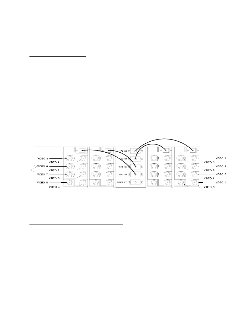
FIBER CONNECTIONS
The fiber optic connection to the user’s infrastructure is made via a SC connector located at the
back of the CWDM unit. Be sure to allow sufficient room for the required minimum bend radius
of the fiber cable used. SC patch cords are supplied for the intra-fiber connections between the
CWDM and each of the 980D series units. The wavelength listed for each port on the CWDM
must correlate with the wavelength listed on the 980D series unit to which that port is attached.
VIDEO INPUT / OUTPUT CONNECTIONS
Video input and output connections are located on the rear of the 980D series units. A BNC
connector is provided for each channel. The video inputs are connected to an appropriate 75
Ω
baseband video source such as a camera or a video recorder output. The 75
Ω video outputs
can be looped through typical baseband video inputs of switchers, recorders and other
equipment as required. For proper operation, the outputs must be terminated with 75
Ω. For
optimum performance the video cables should be the shortest length of coax practical.
The location of a video input to the RT-93200D-SL will be mirrored as a video output at the RR-
93200D-SL. For example, the Video 2 input on the RT-980D-1490 will become the Video 2
output on the RR-980D-1490 after traveling across the fiber infrastructure.