American Fibertek MRX-8623C User Manual
Page 4
4
For mounting the unit flush to a wall or other rigid
surface, the ears may be installed on the sides with
the oval holes flush with the bottom of the unit as in
Figure 2. Mount the ears with the #10 flathead screws
provided. Mount the unit to a rigid surface using #10
(5mm) screws.
POWER SOURCE
The internal power supply accepts universal line voltage. Any mains supply from 100 to 240
VAC, 50 to 60 Hz, may be used without modification or adjustment. A universal power
connector is provided on the rear of the unit to facilitate connection to the power mains.
POWER CONNECTION
The unit is supplied (in the US and UK only) with a three conductor power cord. The “ground”
conductor is directly connected to the chassis.
FIBER CONNECTION
The fiber optic connection is made via a ST connector located at the back of the unit. Be sure to
allow sufficient room for the required minimum bend radius of the fiber cable used.
VIDEO INPUT / OUTPUT CONNECTIONS
Video input and output connections are located on the rear of the unit. A BNC connector is
provided for each channel. Please note that video channels five and six are not used in this unit.
The video inputs are connected to an appropriate 75
Ω baseband video source such as a
camera or a video recorder output. The 75
Ω video outputs can be looped through typical
baseband video inputs of switchers, recorders and other equipment as required. For proper
operation, the outputs must be terminated with 75
Ω. For optimum performance the video cables
should be the shortest length of coax practical.
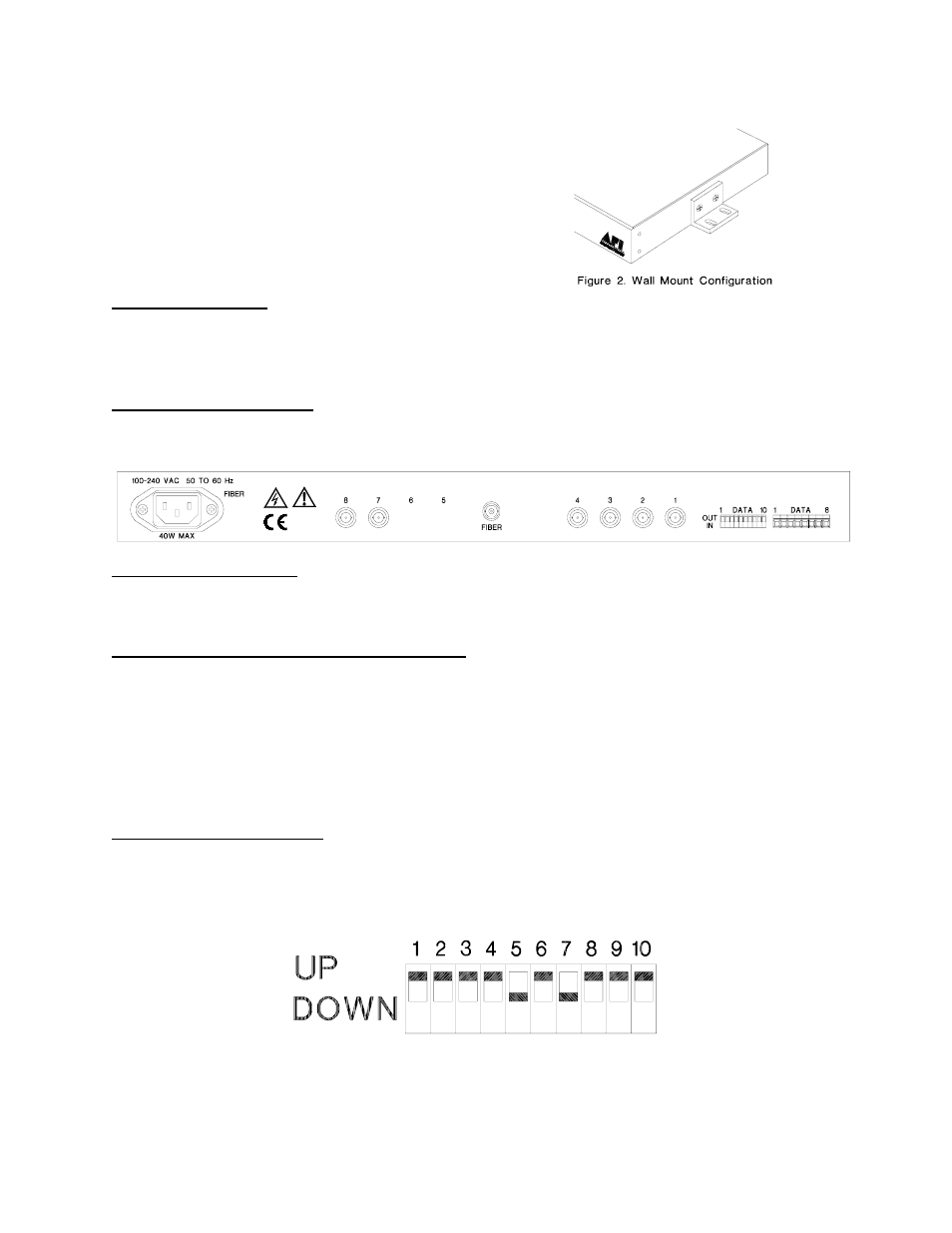
DATA CONFIGURATION
There is a rear panel data configuration switch bank preset at the factory for Manchester and
RS232 data transmission. These switches must remain in the positions shown below to
properly transmit AD/Bosch Manchester and RS232 data.