American Fibertek MRX-986-UTP User Manual
Page 5
5
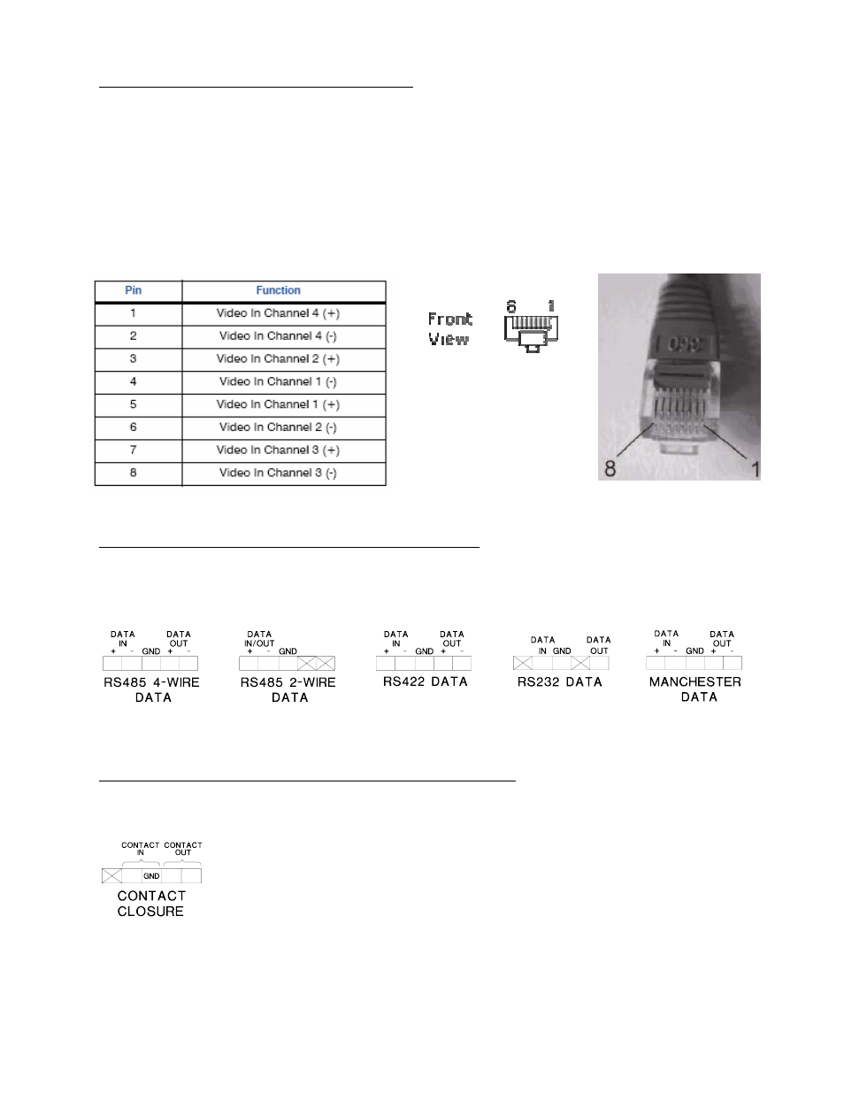
VIDEO INPUT / OUTPUT CONNECTIONS
Video input and output connections are located on the rear of the unit. Video input connections
on the MTX-986-UTP are connected to an appropriate baseband video source such as a
camera or a video recorder output. The video outputs on the MRX-986-UTP can be looped
through typical baseband video inputs of switchers, recorders and other equipment as required.
For optimum performance the video cables should be the shortest length of unshielded twisted
pair cable practical. Use the chart and the drawing below to determine the proper configuration
of the UTP connector wires for insertion into the MTX-986-UTP unit. The bottom UTP port on
the MTX-986-UTP corresponds to video channels 1 through 4, the top corresponds to channels
5 through 8. The video output connectors of the MRX-986-UTP follow the same orientation and
configuration.
DATA INPUT / OUTPUT CONNECTIONS (DATA 1)
Data input and output connections are made via terminal blocks on the back of the unit. See the
drawings below for proper orientation of the input and output connections. Please note that the
far right pin on each connection drawing corresponds with the far right terminal block pin on the
unit.
Please note that Data In on the MTX-986-UTP becomes Data Out on the MRX-986-UTP after
going across the fiber. The reverse flow follows the same orientation.
CONTACT INPUT / OUTPUT CONNECTIONS (DATA 2)
Data input and output connections are made via terminal blocks on the back of the unit. See the
drawing below for proper orientation of input and output connections. Please note that the far
right pin on the connection drawing corresponds with the far right terminal block pin on the unit.
Please note that Contact In on the MTX-986-UTP becomes Contact Out on the MRX-986-UTP
after going across the fiber. The reverse flow follows the same orientation.