American Fibertek MX-481T-SC User Manual
Page 5
5
DATA INPUT / OUTPUT CONNECTIONS
Data input and output connections are made via a terminal block on the right side of the unit. Please
follow the label on the unit for proper orientation of the data connections. Please note RS485 2-wire
data uses the two terminals labeled DATA IN. For RS485 4-wire, DATA IN on the MX-481T-SC
becomes DATA OUT on the remaining MX-481T-SC or RX-481T-SC units after going across the fiber.
The reverse flow follows the same orientation. For 2-wire RS485 format data flows through DATA IN on
both ends.
TYPICAL FOUR WIRE SYSTEM DATA CONNECTIONS
The RS485 four wire interconnection between the MX-481T-SC and the copper device to which it is
attached is based on industry standard EIA terminology for the transmission of electronic data signals.
Using this terminology, the driver of an electronic signal is labeled TX or Data Out. Correspondingly, the
receiver of an electronic signal is labeled RX or Data In. Following this standard, the Data Out of the
copper device is connected to the Data In of the MX-481T-SC. The plus terminal of the copper device is
connected to the plus terminal of the MX-481T-SC and the minus is connected to the minus. The
reverse flow of data from the MX-481T-SC to the copper device follows the same pattern. Not all
manufactures follow standard EIA terminology. Consult the installation instructions for your copper
device if you are unsure which two wires are the drive (data out) wires and which two wires are the
receive (data in) wires.
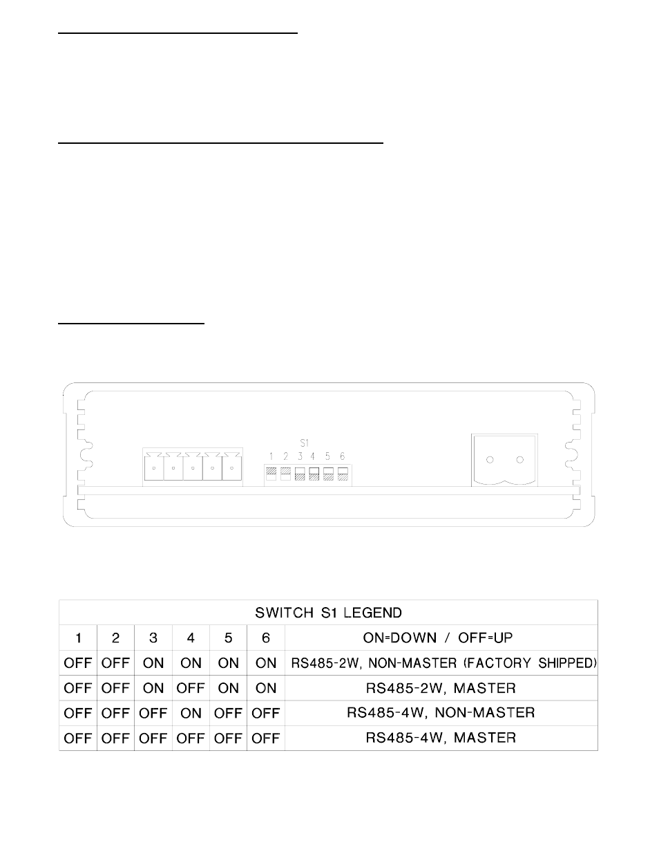
DATA CONFIGURATION
NOTE: This unit is shipped as a ‘non-master’ repeater with the data channel in the RS485 2-wire
configuration. Input termination is set to ON, output termination is set to OFF, and all offset
biasing is set to OFF. The drawing below depicts the configuration switches in their default
settings.
If this unit is connected directly to the host device in this application, or for RS485 4-wire configurations
please refer to the drawing below for changes to the default switch settings of switch bank S1. These
configuration switches are located on the right side of the unit and can be modified without opening the
unit. Switch S1-4 determines the master / ‘non-master’ status of the unit.