American Fibertek MT-388S User Manual
Page 3
3
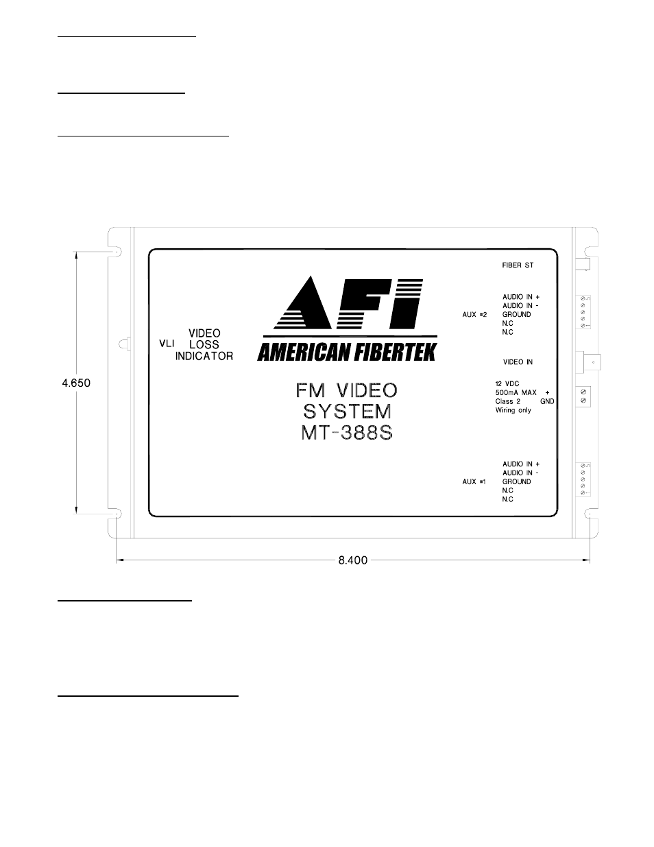
POWER CONNECTION
Power is supplied to the unit via a two pin terminal connector on the side of the unit. See label on unit
for proper location of input power.
FIBER CONNECTION
The fiber optic connection is made via a ST connector located on the side of the unit.
VIDEO INPUT CONNECTION
The video input connection is made via a BNC connector on the side of the unit. The video input should
be connected to an appropriate 75
Ω baseband video source such as a camera or a video recorder
output. The 75
Ω video output can be looped through typical baseband video inputs of switchers,
recorders and other equipment. For proper operation, the output must be terminated with 75
Ω. For
optimum performance the video cables should be the shortest length of coax practical.
AUDIO INPUT LEVELS
The ideal audio input level is 0dBm
600
. (This is 1mW across the 600 Ohm input impedance.) On a
voltage basis, this is equal to 0dBV or 2.19 Vp-p. Higher input levels will cause increased distortion. Up
to +3dBm, the distortion will increase a small amount. Above this level the distortion will increase
rapidly. Lower input signal levels will reduce the signal to noise ratio. In either balanced or unbalanced
configuration, the input impedance is 600 Ohms.
AUDIO INPUT CONNECTIONS
Audio input connections are made via terminal blocks on the side of the unit. In a balanced audio
configuration, the input connection is made across the plus and the minus terminals. In an unbalanced
configuration, the plus terminal is used for the input audio connection with the minus and ground
terminals used for the ground connection. Please note that Audio In on the MT-388S becomes Audio
Out on the MR-388S or RR-388S after going across the fiber. For optimum performance the audio
cables should be the shortest length of wire practical.