American Fibertek MR-388SL User Manual
Page 3
3
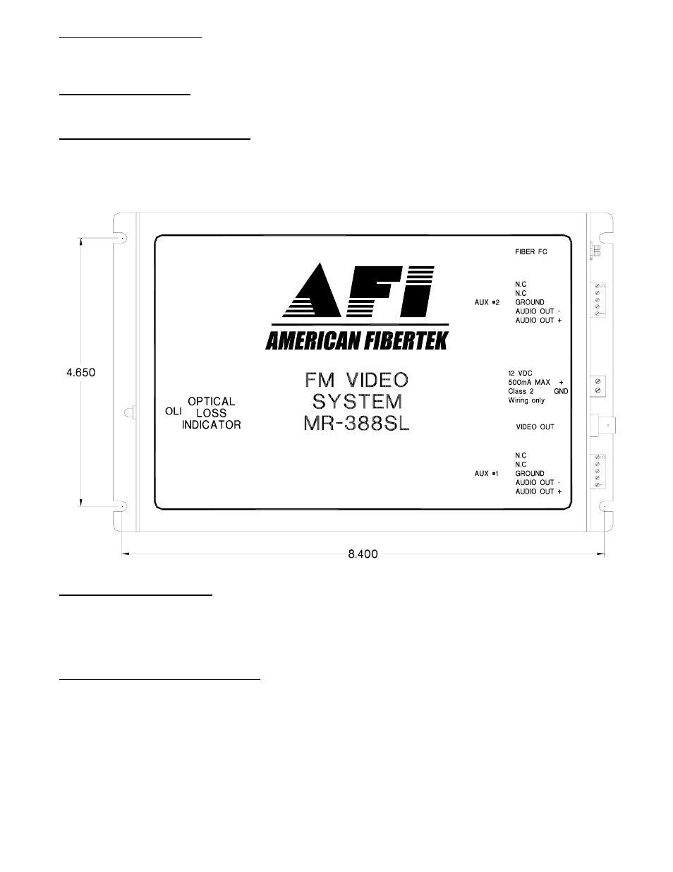
POWER CONNECTION
Power is supplied to the unit via a two pin terminal connector on the side of the unit. See label on unit
for proper location of input power.
FIBER CONNECTION
The fiber optic connection is made via a FC/PC connector located on the side of the unit.
VIDEO OUTPUT CONNECTION
The video output connection is made via a BNC connector on the side of the unit. The 75
Ω video output
can be looped through typical baseband video inputs of switchers, recorders and other equipment. For
proper operation, the output must be terminated with 75
Ω. For optimum performance the video cables
should be the shortest length of coax practical.
AUDIO OUTPUT LEVELS
The audio output signal appears on both the plus and minus terminals of this unit. Half of the signal
appears on each output terminal. The two outputs are 180° out of phase. The balanced output
impedance is 600 Ohms while the unbalanced output impedance is 300 Ohms. The output signal level
will be half of the input level (-6dB) in an unbalanced configuration.
AUDIO OUTPUT CONNECTIONS
Audio output connections are made via terminal blocks on the side of the unit. In a balanced audio
configuration, the output connection is made across both the plus and the minus terminals. To connect
unbalanced, the plus output terminal is used for the audio connection, along with the ground terminal.
Please note that Audio Out on the MR-388SL comes from Audio In on the MT-388SL or RT-388SL
before going across the fiber. For optimum performance the audio cables should be the shortest length
of wire practical.