American Fibertek MTM-61 User Manual
Page 3
3
VIDEO INPUT CONNECTION
The video input connection is made via a BNC connector on the side of the unit. The video input should
be connected to an appropriate 75
Ω
baseband video source such as a camera or a video recorder
output. For optimum performance the video cables should be the shortest length of coax practical.
FIBER CONNECTION
The fiber optic connection is made via a ST connector located on the right side of the unit.
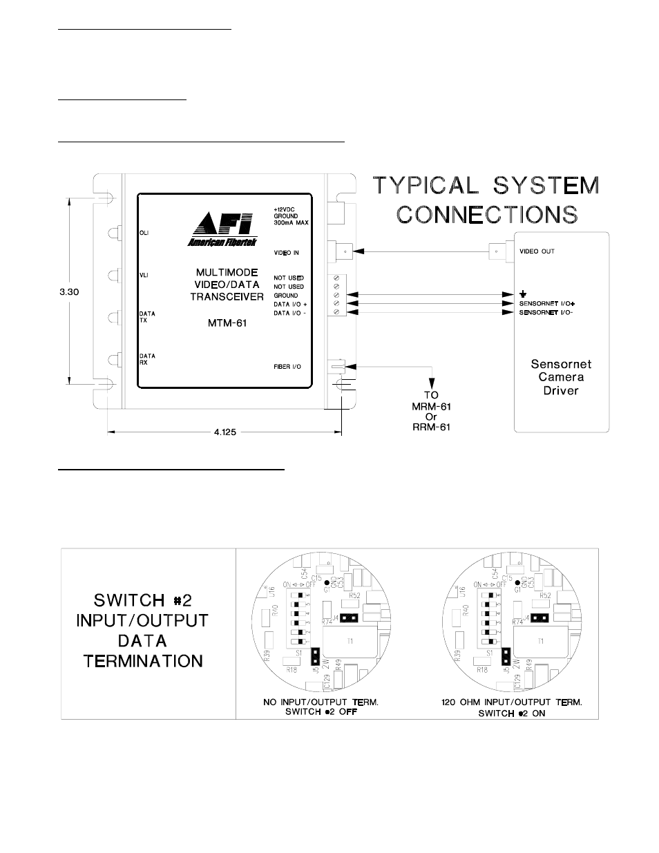
SENSORNET INPUT / OUTPUT CONNECTIONS
Data input and output connections are made via a terminal block on the right side of the unit. Follow
the label on the MTM-61 for proper orientation of Sensornet data input/output wires.
DATA TERMINATION REQUIRMENTS
The MTM-61 is shipped from the factory with internal data input/output 120 ohm termination
switched on. In order to remove the internal termination, the unit needs to be opened up and
switch setting #2 needs to be modified using the internal switch/jumper settings shown below.
There are several other switches on the same switch bank with the data termination switch.
These switches must not be changed. The drawing below indicates their original positions.
To open the MTM-61, remove the screw on the bottom of the module. Also remove two screws holding
the end panel to the chassis on the side with the video and data connections. Slide PCB assembly out
of chassis to access the switch and jumper locations.