American Fibertek RRM-61 User Manual
Page 3
3
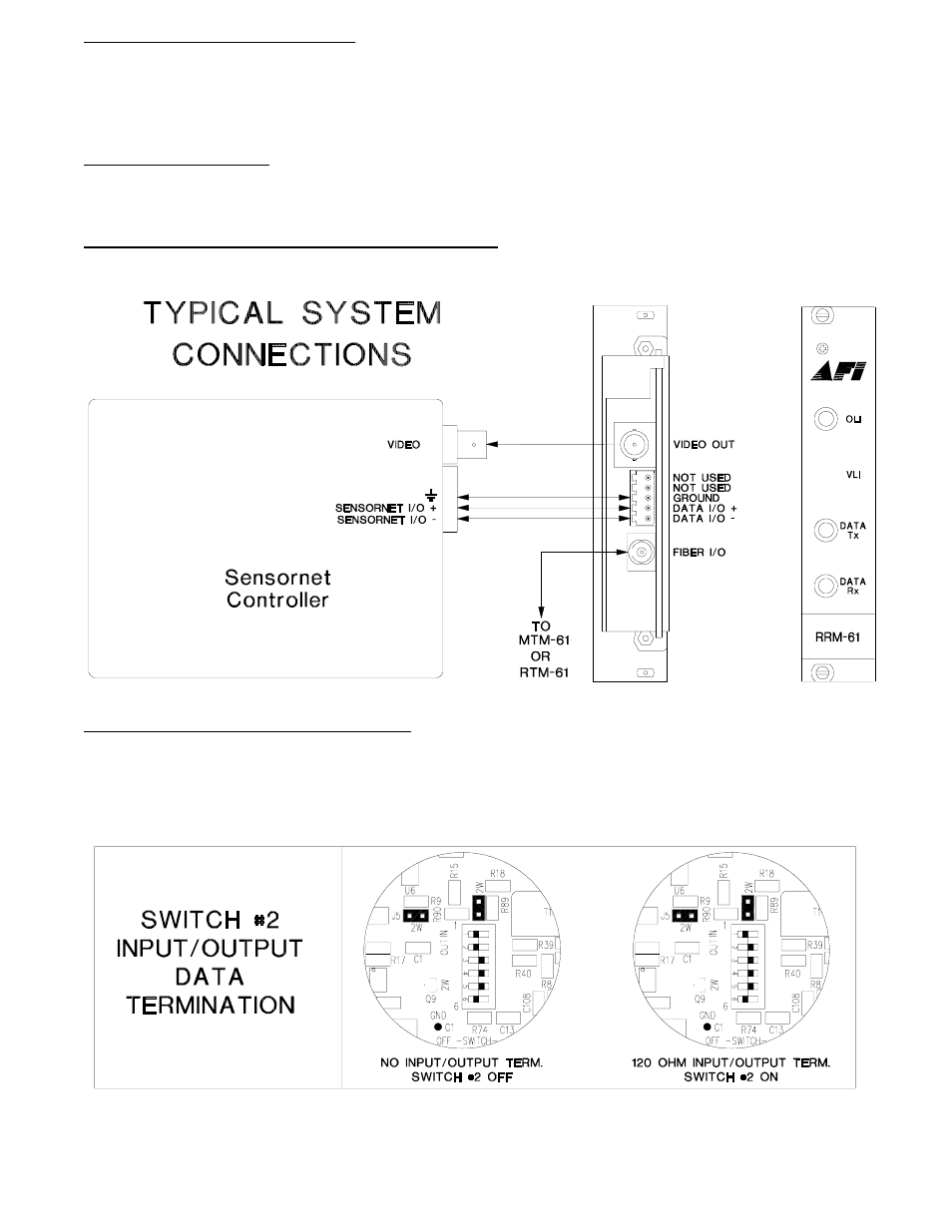
VIDEO OUTPUT CONNECTION
The video output connection is made via a BNC connector on the back of the unit. The 75
Ω
video
output can be looped through typical baseband video inputs of switchers, recorders and other
equipment as required. For proper operation, the output must be terminated with 75
Ω
. For optimum
performance the video cables should be the shortest length of coax practical.
FIBER CONNECTION
The fiber optic connection is made via a ST connector located on the back of the unit. Be sure to allow
sufficient room for the required minimum bend radius of the fiber cable used.
SENSORNET INPUT / OUTPUT CONNECTIONS
Data input and output connections are made via a terminal block on the back of the unit. Follow the
drawing below for proper orientation of Sensornet data input/output wires.
DATA TERMINATION REQUIRMENTS
The RRM-61 is shipped from the factory with internal data input/output 120 ohm termination
switched off. In order to configure the internal termination, the unit needs to be opened up and
switch setting #2 needs to be modified using the internal switch/jumper settings shown below.
There are several other switches on the same switch bank with the data termination switch.
These switches must not be changed. The drawing below indicates their original positions.
To open the RRM-61, remove the three Phillips head screws holding the top cover, then remove the
top cover. The six position switch bank is located near the center of the card.