American Fibertek MRM-1400 User Manual
Page 3
3
POWER CONNECTION
Power is supplied to the unit via a two pin terminal connector. Follow the label on the unit for proper
orientation of +12 volt dc and ground.
VIDEO OUTPUT CONNECTION
The video output connection is made via a BNC connector on the side of the unit. The 75
Ω
video output
can be looped through typical baseband video inputs of switchers, recorders and other equipment as
required. For proper operation, the output must be terminated with 75
Ω
. For optimum performance the
video cables should be the shortest length of coax practical.
FIBER CONNECTION
The fiber optic connection is made via a ST connector located on the side of the unit.
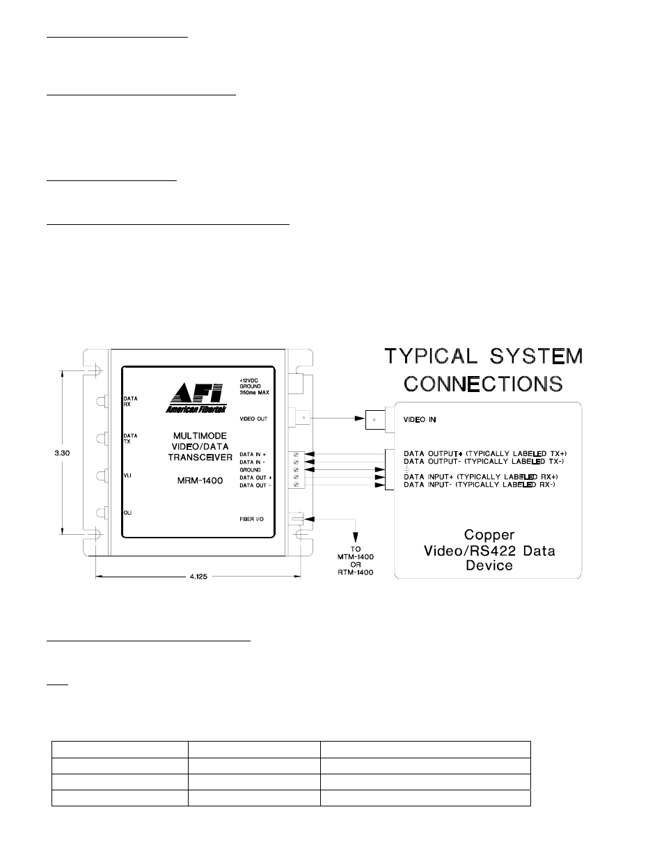
DATA INPUT / OUTPUT CONNECTIONS
Data input/output connections are made via a terminal block on the side of the unit. Follow the label on the
MRM-1400 for proper orientation of data input/output wires. An example of the RS422 interconnection
between the MRM-1400 series unit and the copper device to which it is attached is shown below. This
illustration is based on industry standard EIA terminology for the transmission of electronic data signals.
Using this terminology, the driver of an electronic signal is labeled TX or data out. Correspondingly, the
receiver of an electronic signal is labeled RX or data in. Not all manufactures follow standard EIA
terminology. Consult the installation instructions for your copper device if you are unsure which two wires
are the drive (data out) wires and which two wires are the receive (data in) wires.
Please note that Data In on the MRM-1400 becomes Data Out on the MTM-1400 or RTM-1400 after going
across the fiber. The reverse flow follows the same orientation.
MRM-1400 STATUS INDICATORS
The MRM-1400 provides the following LED status indicators to aid in installation and troubleshooting:
OLI
A bi-color LED indicator monitors the power of the optical input signal that is being received at the MRM-
1400 from the MTM-1400 or the RTM-1400. DC power and optical input status associated with this LED are
summarized below.
Optical Level Indicator
DC Power Status
Optical Status
Green
On
Proper Optical Input Power Present
Red
On
Optical Input Not Detected
Off
Off
Check Power Supply