American Fibertek RTM-1485 User Manual
Page 4
4
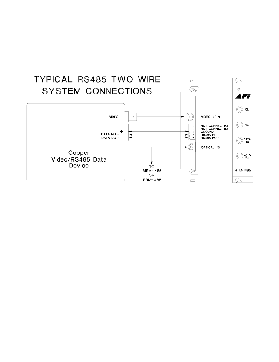
RS485 TWO WIRE INPUT / OUTPUT DATA CONNECTIONS
Data input/output connections are made via a terminal block on the back of the unit. An
example of the RS485 interconnection between the RTM-1485 unit and the copper
device to which it is attached is shown below. This illustration is based on industry
standard EIA terminology for the transmission of electronic data signals.
DATA CONFIGURATION
The RTM-1485 is shipped from the factory in the RS485 4-wire configuration. In
order to configure the unit for RS485 two wire operation, the unit needs to be
opened up and several switch settings and jumper pins need to be modified using
the internal switch/jumper settings shown on the next page.
The RTM-1485 is shipped from the factory with internal data input and output 120
ohm terminations switched on. In order to remove the internal terminations, the
unit needs to be opened up and several switch settings need to be modified using
the internal switch/jumper settings shown on the next page.
See page 7 for an explanation of termination and offset bias requirements for RS485
data. To open the RTM-1485, remove three screws on top cover to remove cover and
access the switch and jumper locations.