American Fibertek RRM-1485 User Manual
Page 3
3
FIBER CONNECTION
The fiber optic connection is made via a ST connector located on the back of the unit.
Be sure to allow sufficient room for the required minimum bend radius of the fiber cable
used.
VIDEO OUTPUT CONNECTION
The video output connection is made via a BNC connector on the back of the unit. The
75
Ω
video output can be looped through typical baseband video inputs of switchers,
recorders and other equipment as required. For proper operation, the output must be
terminated with 75
Ω
. For optimum performance the video cables should be the shortest
length of coax practical.
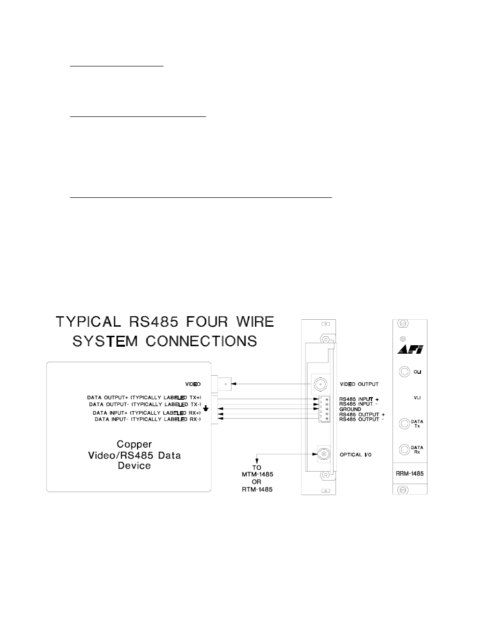
RS485 FOUR WIRE INPUT / OUTPUT DATA CONNECTIONS
Data input/output connections are made via a terminal block on the back of the unit. An
example of the RS485 interconnection between the RRM-1485 unit and the copper
device to which it is attached is shown below. This illustration is based on industry
standard EIA terminology for the transmission of electronic data signals. Using this
terminology, the driver of an electronic signal is labeled TX or data out. Correspondingly,
the receiver of an electronic signal is labeled RX or data in. Not all manufactures follow
standard EIA terminology. Consult the installation instructions for your copper device if
you are unsure which two wires are the drive (data out) wires and which two wires are
the receive (data in) wires.