American Fibertek MTM-1485 User Manual
Page 4
4
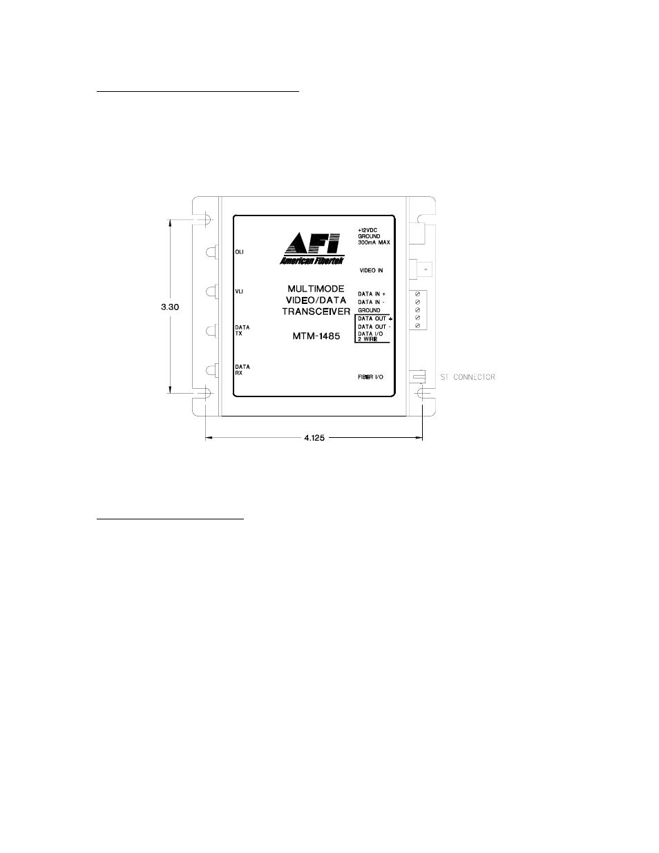
INPUT / OUTPUT CONNECTIONS
The fiber optic connection is made via a ST connector located on the right side of the
unit.
The video input connection is made via a BNC connector on the right side of the unit.
The video input should be connected to an appropriate 75
Ω
baseband video source
such as a camera or a video recorder output. For optimum performance the video
cables should be the shortest length of coax practical.
Data input and output connections are made via a terminal block on the right side of the
unit. Follow label on unit for proper orientation of RS485 data input and output. Please
note that two wire applications utilize the four wire data out + and data out - terminals.
DATA CONFIGURATION
The MTM-1485 is shipped from the factory in the RS485 4-wire configuration. In
order to configure the unit for RS485 two wire operation, the unit needs to be
opened up and several switch settings and jumper pins need to be modified using
the internal switch/jumper settings shown on the next page.
The MTM-1485 is shipped from the factory with internal data input and output 120
ohm terminations switched on. In order to remove the internal terminations, the
unit needs to be opened up and several switch settings need to be modified using
the internal switch/jumper settings shown on the next page.
See page 7 for an explanation of termination and offset bias requirements for RS485
data. To open the MTM-1485, remove the screw on the bottom of the module. Also
remove two screws holding the end panel to the chassis on the side with the video and
data connections. Slide PCB assembly out of chassis to access the switch and jumper
locations.